• Product
  • Suppliers
  • Manufacturers
  • Solutions
  • Free tools
  • Knowledges
  • Experts
  • Communities
Search


High-Voltage DC Contactor Wiring Essentials: Polarity Requirements and Safety Guidelines

Echo
Echo
Field: Transformer Analysis
China

High-Voltage DC Contactors Usually Have Polarity Distinctions

This is especially true in application scenarios with high current and high voltage.

Why Polarity Distinctions Exist

Arc Characteristics

DC current has no zero-crossing point, making arc extinction more difficult than that of AC. Polarity (current direction) may affect the stretching and extinguishing effect of the arc.

Internal Structural Design

Some contactors optimize arc-extinguishing devices (such as magnetic blowout coils and permanent magnets) for current direction. Reverse current may lead to a decrease in arc-extinguishing capability.

Electronic Auxiliary Circuits

Certain contactors integrate electronic arc-extinguishing or surge suppression circuits (e.g., diodes, RC circuits). Incorrect polarity may damage these components.

Consequences of Reverse Connection

  • Arc Extinction Failure: The arc duration is prolonged, which ablates the contacts and shortens the service life.

  • Performance Degradation: The contact resistance increases, and heat generation intensifies.

  • Damage Risk: If electronic components (such as suppression diodes) are included, it may cause short circuits or failures.

Precautions for Using High-Voltage Relays

Inrush Current

Causes of Inrush Current

High-voltage DC relays are generally used in DC-side main circuits of inverters (energy storage), power modules (charging piles), electronic control units (electric vehicles) and other equipment. The DC side of such equipment usually has capacitors, which play roles in energy buffering and power balancing, filtering high-frequency harmonics and noise, maintaining stable DC bus voltage, protecting power devices, and improving the dynamic response of the system. However, this is similar to a capacitive load, which can cause excessive voltage difference across the high-voltage DC relay and thus induce inrush current.

Consequences of Inrush Current

  • Inrush current may cause the contacts of the high-voltage DC relay to stick. When the coil is de-energized, the contacts cannot open and will bounce open automatically after a period of time.

  • Inrush current may cause one-sided sticking of the high-voltage DC relay contacts. When the coil is energized, the relay does not pull in, but the auxiliary contacts remain closed.

  • Inrush current may cause uneven contacts of the high-voltage DC relay, reducing the effective contact area, increasing heat generation, and creating potential safety hazards.

Load-Bearing Interruption

High-voltage DC contactors face more severe challenges during load-bearing interruption (live breaking) than AC contactors. The main reason is that DC current has no natural zero-crossing point, making arc extinction difficult. The following are key points and countermeasures:

Difficulties in Load-Bearing Interruption

  • Sustained Arc: DC current has no zero-crossing point, so the arc may persist for a long time, leading to contact ablation or even welding.

  • High Energy Release: When inductive loads (such as motors and transformers) are de-energized, high induced voltage is generated, which may break down insulation or damage equipment.

  • Polarity Impact: If the contactor is designed for one-way arc extinction, reverse current may exacerbate arc problems.

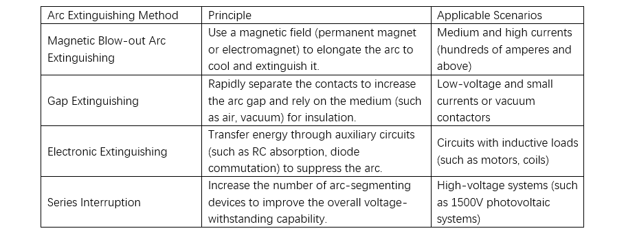
Arc-extinguishing technology of high-voltage DC contactors

Arc-extinguishing technology of high-voltage DC contactors.png

Solutions for Load-Bearing Interruption

Pre-charging Circuit (Common in Electric Vehicles)

Before the main contacts of the contactor close, a pre-charging resistor is used to limit the inrush current and reduce the energy during breaking.

Arc-Extinguishing Auxiliary Circuits

  • RC Snubber Circuit: Connected in parallel with the contacts to absorb inductive energy.

  • Freewheeling Diode: Provides a current loop for inductive loads (note polarity matching).

  • Metal Oxide Varistor (MOV): Limits overvoltage.

Step-by-Step Breaking

First break the small-current auxiliary contacts, then break the main contacts (such as in dual-contact design).

Precautions

  • Current/Voltage Limitation: Ensure the breaking current does not exceed the rated breaking capacity of the contactor (e.g., 1000V/500A); otherwise, it may fail.

  • Polarity Matching: If the contactor is of unidirectional design, it must be energized in the nominal direction; otherwise, the arc-extinguishing capability will decrease.

  • Load Types:

    • Resistive Loads: Easier to break (low arc energy).

    • Inductive Loads: Require additional protection circuits (such as diodes).

    • Capacitive Loads: Be wary of inrush current during closing (may cause contact adhesion).

Give a tip and encourage the author!
Recommended
3D Wound-Core Transformer: Future of Power Distribution
Technical Requirements and Development Trends for Distribution Transformers Low losses, especially low no-load losses; highlighting energy-saving performance. Low noise, particularly during no-load operation, to meet environmental protection standards. Fully sealed designto prevent transformer oil from contacting external air, enabling maintenance-free operation. Integrated protection devices within the tank, achieving miniaturization; reducing transformer size for easier on-site installation. C
Echo
10/20/2025
Reduce Downtime with Digital MV Circuit Breakers
Reduce Downtime with Digitized Medium-Voltage Switchgear and Circuit Breakers"Downtime" — it’s a word no facility manager wants to hear, especially when it’s unplanned. Now, thanks to next-generation medium-voltage (MV) circuit breakers and switchgear, you can leverage digital solutions to maximize uptime and system reliability.Modern MV switchgear and circuit breakers are equipped with embedded digital sensors that enable product-level equipment monitoring, providing real-time insights into the
Echo
10/18/2025
One Article to Understand the Contact Separation Stages of a Vacuum Circuit Breaker
Vacuum Circuit Breaker Contact Separation Stages: Arc Initiation, Arc Extinction, and OscillationStage 1: Initial Opening (Arc Initiation Phase, 0–3 mm)Modern theory confirms that the initial contact separation phase (0–3 mm) is critical to the interrupting performance of vacuum circuit breakers. At the beginning of contact separation, the arc current always transitions from a constricted mode to a diffused mode—the faster this transition, the better the interruption performance.Three measures c
Echo
10/16/2025
Advantages & Applications of Low-Voltage Vacuum Circuit Breakers
Low-Voltage Vacuum Circuit Breakers: Advantages, Application, and Technical ChallengesDue to their lower voltage rating, low-voltage vacuum circuit breakers have a smaller contact gap compared to medium-voltage types. Under such small gaps, transverse magnetic field (TMF) technology is superior to axial magnetic field (AMF) for interrupting high short-circuit currents. When interrupting large currents, the vacuum arc tends to concentrate into a constricted arc mode, where localized erosion zones
Echo
10/16/2025
Send inquiry
Download
Get the IEE Business Application
Use the IEE-Business app to find equipment, obtain solutions, connect with experts, and participate in industry collaboration anytime, anywhere—fully supporting the development of your power projects and business.