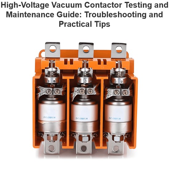
1. Applications of Low-Voltage Vacuum Contactors
Low-voltage vacuum contactors are suitable for power systems with an AC frequency of 50Hz and a rated operating voltage of 1140V, 660V, 500V, or 380V in the main circuit. They are used for remotely and frequently connecting and disconnecting circuits, as well as controlling three-phase AC motors or other electrical equipment. They are particularly applicable to locations with heavy loads and frequent operations.
2. Structure of Low-Voltage Vacuum Contactors
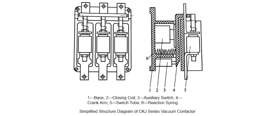
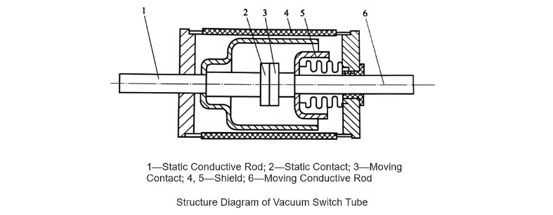
As shown in the above diagram, the low-voltage vacuum contactor is mainly composed of a switch tube, closing coil, auxiliary switch, reaction spring, crank arm, base, etc. Among them, the key component, the vacuum switch tube, is a tubular part. Inside the sealed shell, there are moving and static contacts, a shielding cover, conductive rods for moving and static contacts, etc. The structure diagram of the vacuum switch tube is shown in the following diagram.
3. Working Principle of Low-Voltage Vacuum Contactors
When the operating coil of the mechanism is energized, the armature of the electromagnet is attracted. Through the transmission mechanism connected to the moving armature plate, the conductive rod of the arc-extinguishing chamber of the three-phase vacuum switch tube is driven to move upward, resulting in the contactor closing. After the coil is de-energized, the armature is released under the action of the opening spring, and the transmission mechanism drives the conductive rod of the arc-extinguishing chamber to move downward, causing the contactor to open. In this way, the on-off control of the controlled circuit is realized, and its electrical principle is shown in the following diagram.
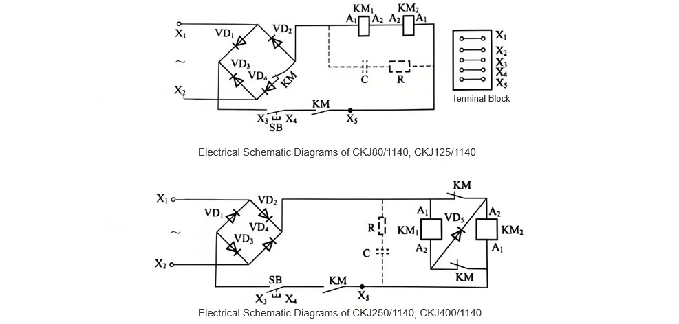
If the control power supply voltage is 380V, a resistor-capacitor (RC) absorption device needs to be connected in parallel across the electromagnetic coil; if the control power supply voltage is 36V, 110V, or 220V, but sparking at the auxiliary switch is not desired, an RC absorption device can also be connected in parallel across the electromagnetic coil (indicated by dashed lines).
4. Fault Diagnosis and Maintenance of Low-Voltage Vacuum Contactors
4.1 Failure to Operate
If the power supply voltage is too low, increase the power supply voltage.
If the power supply voltage does not match the contactor's rated voltage, correct the power supply voltage or replace the vacuum contactor.
If the circuit wiring is incorrect, check the wiring diagram and correct the wiring.
If the connecting wires are not properly connected or the screws are loose, inspect the wiring and tighten the screws.
If the control contacts have poor contact, check the contact resistance and clean the contacts.
If the fuse element is blown, replace the fuse element.
If the coil is burned out, replace the coil.
If the diode is broken down, replace the diode.
If the switch tube is damaged, check whether there is negative pressure in the switch tube and replace the switch tube if necessary.
4.2 Failure to Trip
If the power supply voltage is too low, increase the power supply voltage.
If the power supply voltage does not match the contactor's rated voltage, correct the power supply voltage or replace the vacuum contactor.
If the circuit wiring is incorrect, correct the wiring.
If the coil is burned out, replace the coil.
4.3 Overheating of the Coil, or Even Burning Out
If the power supply voltage does not match the coil's rated voltage, correct the power supply voltage to make it consistent with the coil's rated voltage.
If the connecting wires are not properly connected or the screws are loose, inspect the circuit and tighten the screws.
If the auxiliary switch contacts are damaged or fail to operate, inspect the auxiliary switch and replace it if necessary.
4.4 Surface Leakage of the Switch Tube
If there are foreign objects or water attached to the surface of the switch tube, causing surface leakage, measure the insulation resistance of the switch tube and clean the outer shell of the switch tube.
4.5 Diode Breakdown
If the power supply voltage does not match the diode's rated voltage, causing diode breakdown, correct the power supply voltage or replace the diode with one that matches the voltage.
4.6 Overheating of Energized Parts
If overheating is caused by poor contact of connecting wires, carefully inspect the circuit and tighten the screws to ensure good contact.


