What Happens When a Vacuum Circuit Breaker Loses Vacuum? Real Test Results Revealed

What Happens When a Vacuum Interrupter Loses Its Vacuum?
If a vacuum interrupter loses its vacuum, the following operational scenarios should be considered:
Contacts opening
Closing operation
Closed and operating normally
Opening and interrupting normal current
Opening and interrupting a fault current
Cases a, b, and c are relatively straightforward. In these situations, the system is generally unaffected by the loss of vacuum.
However, cases d and e require further discussion.
Assume a three-phase feeder vacuum circuit breaker loses vacuum in one pole. If the load served by the faulty breaker is a delta-connected (ungrounded) load, switching operations will not lead to a failure. Essentially, nothing happens. The two healthy phases (e.g., Phase 1 and Phase 2) successfully interrupt the circuit, and current in the faulty phase (Phase 3) ceases naturally.
A different situation arises with grounded loads. In this case, interruption by the two healthy phases does not stop current flow in the faulty phase. An arc persists in Phase 3 with nothing to extinguish it, and this current continues until backup protection operates. The result is typically catastrophic damage to the breaker.
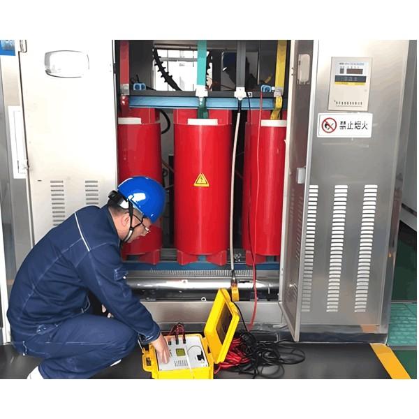
Since vacuum circuit breakers in the 3–15 kV range are primarily used in grounded systems, we investigated the effects of a failed interrupter in our test laboratory years ago. We deliberately exposed a vacuum interrupter to atmospheric pressure ("flattened" it) and then subjected the breaker to a full short-circuit interruption test.

As predicted, the "flat" interrupter failed to clear the fault in the affected phase and was destroyed. The laboratory backup breaker successfully cleared the fault.
After the test, the breaker was removed from the switchgear cell. It was heavily sooted but mechanically intact. Smoke and soot were cleaned from the breaker and switchgear, the faulty unit was replaced, and the breaker was reinserted into the compartment. Later that same day, another short-circuit test was performed—successfully. Years of subsequent field experience have confirmed the findings from these laboratory tests.
One of our customers, a major chemical company, experienced isolated failures on similar circuit configurations (one with an air-magnetic breaker, one with a vacuum breaker) at two different facilities in different countries. Both shared a common circuit configuration and failure mode: a tie circuit where the power sources on either side of the breaker were out of synchronism, applying nearly twice the rated voltage across the contact gap. This caused breaker failure.
These failures resulted from application conditions violating ANSI/IEEE guidelines and far exceeding the breaker’s design ratings. They do not indicate a design flaw. However, the extent of damage is instructive:
In the air-magnetic breaker case, the unit’s enclosure ruptured violently. Adjacent switchgear cells on both sides suffered extensive damage, requiring major reconstruction. The breaker was a total loss.
In the vacuum breaker case, the failure was significantly less violent. The faulty vacuum interrupter was replaced, arc byproducts (soot) were cleaned from the breaker and compartment, and the system was returned to service.
Our extensive laboratory testing, where we routinely push vacuum interrupters to their limits, supports these real-world results.
Recently, several high-power tests were conducted in our lab to evaluate interruption attempts using "leaking" vacuum interrupters. A small hole (~3 mm diameter) was drilled into the interrupter housing to simulate vacuum loss. Results were revealing:
A 1,310 A normal current (rated continuous current: 1,250 A) was interrupted by one pole of a vacuum breaker. Current flowed through the "faulty" breaker for 2.06 seconds before the lab backup breaker cleared the fault. No parts were ejected, the breaker did not explode, and only the paint on the interrupter housing blistered. No other damage occurred.
A second pole of the same breaker attempted to interrupt 25 kA (rated breaking current: 25 kA). The arc lasted 0.60 seconds before the lab breaker cleared the fault. The arc burned a hole through the side of the interrupter housing. No explosion or flying debris occurred. Glowing particles were ejected from the hole, but no mechanical components or adjacent breakers were damaged. All damage was confined to the failed interrupter.
These tests confirm that the consequences of a vacuum interrupter failure are significantly less severe compared to failures in other interrupting technologies.

But the real question is not what happens when it fails, but how likely is it to fail?
Vacuum interrupter failure rates are extremely low. Vacuum loss is no longer a significant concern.
In the early 1960s, vacuum interrupters were prone to leaks—this was a major issue. Early designs used brazed or welded joints between dissimilar materials, with no organic materials. Handcrafting was common, especially with borosilicate glass insulators, which couldn’t withstand high temperatures.
Today, machine welding and batch induction furnace brazing are used with extremely strict process controls. The only moving part inside a vacuum interrupter is the copper contact, connected to the end plate via a welded stainless steel bellows. Since both ends of the bellows are welded, the failure rate of this moving seal is exceptionally low—demonstrating the high reliability of modern vacuum circuit breakers.

In fact, the MTTF (Mean Time To Failure) of modern vacuum interrupters is now estimated at 57,000 years.
Customer concerns about vacuum loss were valid in the 1960s, when vacuum breakers were new to power applications. At that time, vacuum interrupters often leaked, and surge issues were common. Only one company offered vacuum breakers, and reports indicated numerous problems.
By the mid-1970s, European-developed vacuum interrupters—like modern Siemens designs—differed fundamentally from 1960s models in materials and process control. Copper-bismuth contacts were more surge-prone than today’s chromium-copper alloys. Hand-built interrupters were more prone to leaks than today’s precision-manufactured units.
Today, rigorous process control and automation have eliminated most human variability. As a result, modern vacuum interrupters offer long service life, and the dielectric stress they impose on connected equipment is no worse than that of traditional air-magnetic or oil circuit breakers.