Common-mode Electromagnetic Interference Mitigation for Solid-state Transformers

03/07/2024

     This article addresses this gap by presenting a comprehensive review of common dc-link MLCs, covering their topological evolution, features, topologies comparison, modulation techniques, control strategies, and industrial application areas.  Additionally, future perspectives and recommendations are discussed to provide researchers and engineers with a better understanding of the potential applications and advantages of these converters.

1.Introduction.

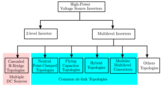
     Considering the major evolutionary stages of MLCs, the existing MLC topologies can be categorized into some families,as shown in the following figure.The first family includes CHB-based topologies and has been. These converters feature high modularity and an optimal number of power switches for output levels [31]. However, multiple isolated DC sources are required, necessitating the use of bulky isolation transformers or limiting their employability to applications that have several isolated DC sources. In addition, uneven power sharing between the cascaded power cells is one of the common challenges in this family. The second family includes NPC-based topologies such as 3L-NPC and 3L-T2C converters. These converters are characterized by robust power circuits and straightforward protection. However, dc-link balancing is an essential requirement in the control design of these topologies. FC-based topologies use capacitors as clamping components to increase the number of levels, forming an MLC family characterized by high flexibility, high redundancies and fault-tolerant operation. Hybrid MLCs are formed by basic cells of the conventional topologies and, therefore, combine several advantages of classical MLCs with the capability to produce a high number of levels. MMC topologies constitute an MLCs family that represents a breakthrough for HV applications due to its high efficiency and high modularity.

Classification of high-power voltage source inverters.png

2. Common Dc-Link Topologies.

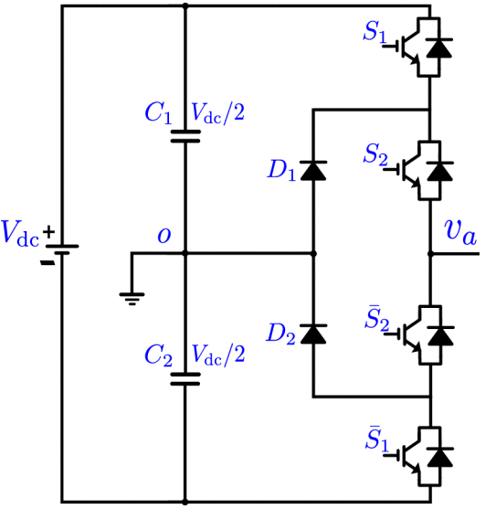
   The three-level Active NPC (ANPC) structure has been able to address the issue of power loss sharing through the use of two different modulation techniques called modulation patterns I and II. In which the two clamping diodes are replaced with two active switches to control the current flow direction in zero states. Modulation pattern I cause most of the switching loss to occur in the outer switches of each leg, while pattern II moves the switching losses to the inner switches.Fc category includes the topologies that employ FCs without a clamped neutral point and, accordingly, do not bring the issue of dc-link balancing. In these topologies, FCs are used to replace the dc-sources while generating voltage levels. In general, thanks to the modularity, this family has the capability to generate relatively higher levels compared to the NPC family. Moreover, flexibility, fault-tolerant operation, and improved loss sharing between switches are prominent features of these topologies.Hybrid multilevel converters (HMLCs) combine multiple fundamental topologies to make use of their respective advantages, while overcoming some of their limitations. Predominantly, hybrid topologies can improve the voltage balancing capabilities for both dc-link and FCs and the power loss distribution across switches, while reducing the number of required active and passive components when compared to NPC and FC topologies .

One phase-leg of the conventional three-level NPC inverter.png

3. Modulation and Control.

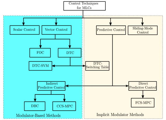
    A classification of the major control techniques for multilevel converters is show in the picture below. As with the two-level converter, the cascaded control structure usually consists of outer and inner control stages in addition to the modulator block. Although the inner and outer loops are similar in the two-level and multilevel converters, the modulator stage, which is mainly required for scalar and field-oriented control (FOC) techniques, needs to be adapted as the number of levels goes higher. In this section, first, a review of the most popular, as well as advanced modulators, is presented. Also, the control techniques that do not require a separate modulator will be investigated in more detail.

Common Control Techniques of Multilevel Converters.png

4. Industrial Applications.

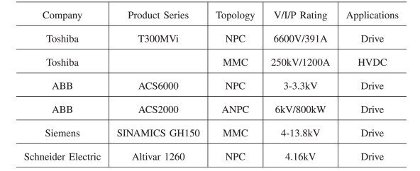
    Historically, CHB inverters are characterized by their modularity, fault tolerance, and ability to generate a high number of voltage levels by cascading cells. However, the requirement of multiple isolated DC sources (rectifier+transformer from the industry point of view) limits their applicability for a vast range of power ratings. Indeed, CHB inverters are mostly employed in high-power applications (ranging from hundreds of kilowatts to megawatts) where there are no available components for such ratings. On the other side, common dc-link topologies are characterized by the employment of a single DC source making them a good alternative in various applications such as 3-phase industrial systems. Indeed, they can be employed in many configurations such as 3-Leg 3-Wire, 3-Leg 4-Wire, and 4-Leg 4-Wire in motor drives, PV inverters, fast DC chargers, etc.

Common DC-Link MLCs in Industry.png


Source: IEEE Xplore

Statement: Respect the original, good articles worth sharing, if there is infringement please contact delete
.

Hey there! I'm an electrical engineer specializing in Failure and Maintenance. I've dedicated my career to ensuring the seamless operation of electrical systems. I excel at diagnosing complex electrical failures, from malfunctioning industrial motors to glitchy power distribution networks. Using state - of - the - art diagnostic tools and my in - depth knowledge, I pinpoint issues quickly. On this platform, I'm eager to share my insights, exchange ideas, and collaborate with fellow experts. Let's work together to enhance the reliability of electrical setups.

Constant testing of high-voltage cable lines
1. Definition of High-Voltage Cable Line Constant TestingHigh-voltage cable line constant testing refers to the systematic measurement, using specialized instruments, of electrical parameters such as resistance, inductance, capacitance, and conductance before a cable line is commissioned or after major maintenance. The aim is to obtain fundamental data characterizing the electromagnetic properties of the cable, serving as a critical testing phase that provides accurate parameter support for powe
09/03/2025
Technical Analysis of 220 kV High-Voltage Cable Construction in Winter
1.Work Environment Requirements and Safeguard MeasuresBased on technical requirements for cable equipment storage, laying, transportation, laying, transposition, testing, and cable terminations, the project owner and construction units have conducted extensive trials and implemented protective measures regarding ambient temperature, humidity, bending radius, traction control, and route optimization. These measures ensure high-voltage cable quality and on-site safety under harsh winter conditions
09/03/2025
Withstand voltage test of high-voltage cables
Withstand voltage test is an insulation test, but it is a destructive test that can reveal insulation defects difficult to detect in non-destructive testing.The test cycle for high-voltage cables is three years, and it must be conducted after non-destructive tests. In other words, the withstand voltage test is performed only after all non-destructive tests have been passed.Most high-voltage cables used today are cross-linked polyethylene (XLPE) cables, which can have large cross-sections and cov
09/03/2025
Analysis of Abnormal Causes of High-Voltage Cable Grounding Circulation and Typical Cases
I. Introduction to Cable Grounding Loop CurrentCables rated 110 kV and above use a single-core structure. The alternating magnetic field generated by the operating current induces a voltage on the metallic sheath. If the sheath forms a closed circuit through the earth, a grounding loop current will flow on the metallic sheath. Excessive grounding loop current (loop current exceeding 50 A, more than 20% of the load current, or a ratio of maximum-to-minimum phase current greater than 3) not only a
09/03/2025
Inquiry
Download
IEE-Business is dedicated to serving the personnel in the global power industry.
Join IEE-Business, not only can you discover power equipment and power knowledge, but also canhnd like - minded friends!