"Faults of catenary isolating switches" are common failures in current traction power supply operations. These faults frequently result from mechanical failures of the switch itself, control circuit malfunctions, or remote control function failures, leading to refusal-to-operate or unintended operation of the isolating switch. Therefore, this paper discusses common faults of catenary isolating switches during current operations and the corresponding handling methods after fault occurrence.
1.Common Faults of Catenary Isolating Switches
1.1 Mechanical Failures (High contact resistance in the isolating switch circuit, poor lead connections, cracked or exploded support insulators)
1.1.1 As the catenary isolating switch is a major component of the power supply line, excessive loop resistance in the catenary circuit manifests specifically as follows: when an electric locomotive draws current from the line, the contacts overheat and burn due to excessively high contact resistance in the circuit, resulting in loss of power supply, catenary power outage, interruption of train operations, and railway power supply accidents.
1.1.2 Poor contact or breakage of leads, burnt wire clamps, or poor contact between leads and clamps of the catenary isolating switch can prevent traction power supply from delivering power to the catenary line, similarly causing catenary faults and affecting train operations.
1.1.3 Support insulators of the catenary isolating switch, if contaminated, damp, or cracked over a long period, may cause flashover due to insufficient insulation to ground, triggering tripping of the traction substation, catenary power outage, and disruption of train operations.
1.2 Control Circuit Failures
The control circuit of the catenary isolating switch includes components such as motors, relays, and power switches. Control circuit failures mainly occur in the secondary control circuit, including lack of power supply in the secondary circuit, loose terminals, internal motor failure, and malfunction of contactor or open/close buttons, all of which can cause equipment failure.
1.3 Remote Communication Failures
1.3.1 Failures of Catenary Switch Monitoring and Control Terminal (RTU).Common RTU failures include:
RTU communication interruption
False reporting of the open/close status of the catenary switch body or miniature circuit breaker;
Loss of external power supply
1.3.2 Optical Cable and Power Cable Failures
Common failures include:
Optical fiber cable break;
Power cable failure;
Charging module failure.
2.Handling Methods for Common Faults of Catenary Isolating Switches
2.1 Handling Methods for Mechanical Failures
Strengthen inspection, testing, and patrol of catenary isolating switches. Perform regular cleaning and maintenance annually; for heavily polluted areas, clean and maintain every 3 months; for lightly polluted areas, every 6 months. During maintenance, focus on checking bolts at upper and lower connection points and tighten them using a torque wrench. The tightening torque of all connecting bolts must comply with the values specified in Table1 to prevent loose connections that could cause equipment discharge.
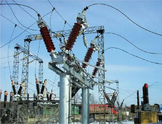
Check the sag, integrity, and insulation distance of the switch leads. To address increased contact resistance causing overheating, focus on measuring loop resistance at the contact parts during testing: when the test current is 100A, the loop resistance at the contact point should not exceed 50μΩ. Inspect the contacts, gently wipe them with gasoline and a cloth, then apply petroleum jelly. Use a 0.05×10mm feeler gauge to check the tightness of contact between contact fingers and contacts. In practice, inadequate maintenance and testing have led to burned isolating switches, as shown in Figure 1 below:
| Bolt Specification (mm) | M8 | M10 | M12 | M14 | M16 | M18 |
M20 |
M24 |
| Torque Value (N.m) | 8.8-10.8 | 17.7-22.6 | 31.4-39.2 | 51.0-60.8 | 78.5-98.1 | 98.0-127.4 | 156.9-196.2 | 274.6-343.2 |
2.2 Handling Methods for Control Circuit Failures
Check for damage to secondary wiring in the control circuit. Verify normal motor rotation. Inspect contactors, auxiliary switches, and open/close buttons for damage. Ensure correct switching and reliable contact of auxiliary switches. Check for loose electrical wiring connections, clear secondary labeling, and correct wiring. Tighten secondary terminal connections. In the mechanical transmission system, inspect linkages, clamps, and crossovers for deformation or corrosion, and ensure threads are undamaged. The key to addressing all control circuit failures is thorough inspection, cleaning, and maintenance. After completion, manually and electrically operate the switch open and closed three times each to ensure reliable operation.
2.3 Handling Methods for Remote Communication Failures:
2.3.1 When RTU communication is interrupted, first check the RTU power supply to see if the circuit breaker has tripped. If not tripped, check whether the indicator lights on the RTU module are blinking normally. If the indicator lights are abnormal, check whether the RTU monitoring terminal has crashed due to prolonged operation. Restart the RTU and observe if it operates normally. If it still fails to operate normally (TX/RX transmit/receive indicator lights not blinking), the internal transmit/receive nodes of the RTU module are likely damaged and require replacement of the RTU monitoring terminal to verify functionality.
2.3.2 When false reports occur regarding the open/close status of the catenary switch body or miniature circuit breaker, first verify whether the switch body and miniature circuit breaker are in normal condition. If they are correctly positioned, check whether the RTU remote signal secondary terminal blocks (KF1/KH1/KC1)/(YX1/YX2) are loose. Check whether the miniature circuit breaker can close properly. If it operates normally, its status is good. Normally, the miniature circuit breaker should be in the open position. When false alarms occur, inspect the RTU remote signal terminals (KF2/KH2/KC2)/(YX3/YX4) for looseness.
2.3.3 In case of external power loss, check whether the incoming power source (through-line or substation) has phase loss or power outage. Inspect the cable burial route for damage. Use continuity testing to check whether foundation settlement has caused grounding or short-circuiting of the power cable. Also check whether the RTU secondary terminal block (YX15/COM) is loose.
2.3.4 In case of optical fiber cable failure, use an Optical Time Domain Reflectometer (OTDR) to inspect whether the buried optical cable path has been damaged. Regularly test fiber optic attenuation using an optical power meter. Check the tail fibers inside the RTU terminal box for bending or damage, and replace tail fibers periodically.
3.Conclusion
Catenary isolating switches are now widely used in electrified railway operations and have become an indispensable part of railway traction power supply. How to prevent faults in catenary isolating switches and how to handle them effectively after occurrence—thereby reducing fault frequency, minimizing outage duration, and mitigating impact on railway transportation—requires our continuous efforts, enhanced learning, experience accumulation, and mastery of operational faults of catenary isolating switches to ensure smooth railway operations.