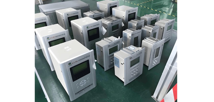
What is a microcomputer protection device?
Answer: A microcomputer protection device is an automatic device that can detect faults or abnormal operating conditions in electrical equipment within a power system, and act to trip circuit breakers or issue alarm signals.
What are the basic functions of microcomputer protection?
Answer:
Automatically, rapidly, and selectively isolate faulty equipment from the system by tripping circuit breakers, ensuring non-faulty equipment resumes normal operation quickly and preventing further damage to the faulty equipment.
Detect abnormal operating conditions of electrical equipment, and based on operational maintenance requirements, trigger alarm signals or disconnect equipment that might be damaged or develop into faults if continued in service. Relay protection responding to abnormal conditions usually does not require immediate action and may include a time delay.
What are the fundamental requirements for microcomputer protection?
Answer: Microcomputer protection plays a critical role in ensuring the safe, stable, and reliable operation of power systems and in promptly clearing faults. Therefore, relay protection must meet the following requirements:
Selectivity: When a system fault occurs, the protection device should only isolate the faulty equipment, ensuring non-faulty equipment continues to operate, thereby minimizing the outage area and achieving selective operation.
Speed: After a system fault, if the fault is not quickly cleared, it may escalate. For example, during a short circuit, voltage drops significantly, causing motors near the fault point to slow down or stall, disrupting normal production. Additionally, generators cannot deliver power during a fault, potentially leading to system instability. Furthermore, faulted equipment carries high fault currents, suffering severe mechanical and thermal damage. The longer the fault current persists, the more severe the damage. Therefore, after a fault, the protection system should act as quickly as possible to isolate it.
Sensitivity: The protection device must reliably detect faults and abnormal conditions within its protected zone. This means it should operate sensitively not only during three-phase metallic short circuits under maximum operating conditions, but also during two-phase short circuits with high transition resistance under minimum operating conditions, maintaining sufficient sensitivity and reliable operation.
Reliability: The reliability of a protection system is crucial. It must not fail to operate when a fault occurs within its protection zone, nor should it operate incorrectly when no fault exists. An unreliable protection device, once in service, could itself become a source of expanded or even direct accidents.
Briefly describe the microcomputer-based protections used for transformers and their respective functions.
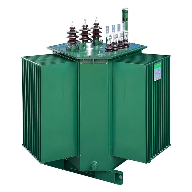
Answer: Transformers are vital equipment in power systems. Their faults severely impact power supply reliability and normal system operation. Large-capacity transformers are also extremely valuable, so protection devices with excellent performance and high reliability must be installed based on transformer capacity and importance.
Transformer faults can be classified into internal and external faults within the tank.
Internal tank faults mainly include:Phase-to-phase short circuits, turn-to-turn short circuits, and single-phase ground faults. Short-circuit currents generate arcs that can burn windings, insulation, and the core, and may cause intense vaporization of transformer oil, potentially leading to tank explosions.
External tank faults include:Phase-to-phase and single-phase ground faults on bushings and outgoing leads.
Abnormal operating conditions include:Overcurrent due to external short circuits, overloading due to various reasons, and low oil level inside the tank.
Based on these fault types and abnormal conditions, the following protection devices should be installed:
Gas (Buchholz) protection for internal tank short circuits and low oil levels.
Longitudinal differential protection or instantaneous overcurrent protection for multi-phase short circuits in windings and leads, ground faults on windings and leads in high-current grounding systems, and turn-to-turn short circuits.
Overcurrent protection (or overcurrent protection with compound voltage start or negative-sequence current protection) for external phase-to-phase short circuits, serving as backup for gas and differential (or instantaneous overcurrent) protection.
Zero-sequence current protection for external ground faults in high-current grounding systems.
Overload protection for symmetrical overloads, etc.
What protections are installed for a 600MW generator-transformer (gen-transformer) unit?
Answer:
Generator-transformer unit differential protection
Generator longitudinal differential protection
Main transformer differential protection
Generator loss-of-excitation protection
Generator out-of-step protection
Generator reverse power protection
Generator low-frequency protection
Over-excitation protection
Generator stator ground fault protection
Generator overcurrent protection
Generator inverse-time negative-sequence overcurrent protection
Generator stator overload protection
Generator water-loss protection
Main transformer neutral-point zero-sequence current protection
Main transformer gas (Buchholz) protection
Main transformer pressure relief protection
What are the differences between main transformer differential and gas protection? Can both protections detect internal transformer faults?
Answer: Differential protection is the primary protection for transformers; gas protection is the main protection for internal transformer faults.
The protection range of differential protection covers the primary electrical equipment between the current transformers on all sides of the main transformer, including:
Multi-phase short circuits on transformer leads and windings
Severe turn-to-turn short circuits
Ground faults on winding leads in high-current grounding systems
The protection range of gas protection includes:
Internal multi-phase short circuits in the transformer
Turn-to-turn short circuits, and short circuits between turns and the core or outer shell
Core faults (such as overheating and damage)
Low oil level or oil leakage
Poor contact in tap changers or defective welding of conductors
Differential protection can be installed on transformers, generators, bus sections, and transmission lines, while gas protection is unique to transformers.
For internal transformer faults (except minor turn-to-turn short circuits), both differential and gas protection can respond. Because internal faults cause oil movement and increased primary current, both protections may activate. Which one operates first depends on the nature of the fault.
What types of faults do main transformer neutral-point zero-sequence overcurrent, gap overcurrent, and zero-sequence overvoltage protect against? What are the setting principles?
Answer: Main transformer neutral-point zero-sequence overcurrent, gap overcurrent, and zero-sequence overvoltage protections are designed to protect against ground faults on the equipment's own outgoing lines. They generally serve as backup protection for grounding faults in the 110–220 kV system on the high-voltage side of the transformer. Zero-sequence current protection is used when the transformer neutral is grounded; zero-sequence voltage protection is used when the neutral point is ungrounded; and gap overcurrent protection is used when the transformer neutral is grounded through a spark gap.
The zero-sequence overcurrent protection has a small starting current, typically around 100 A, with an operating time of about 0.2 seconds. Zero-sequence overvoltage protection is typically set at twice the rated phase voltage. To avoid transient overvoltages during single-phase grounding, the time delay is usually set to 0.1–0.2 seconds. The spark gap length at the 220 kV side neutral point of a transformer is generally 325 mm, with a breakdown voltage RMS of 127.3 kV. When the neutral voltage exceeds the breakdown voltage, the gap breaks down, allowing zero-sequence current to flow through the neutral point. The protection time is set to 0.2 seconds.
What are primary protection and backup protection?
Answer: Primary protection refers to protection that, upon a short-circuit fault, meets system stability and equipment safety requirements, and selectively trips to clear faults on the protected equipment and entire line.
Backup protection refers to protection that clears faults when the primary protection or circuit breaker fails to operate.
What is the function of generator forced excitation?
Answer:
Enhances power system stability.
Enables rapid voltage recovery after fault clearance.
Improves the reliability of time-delayed overcurrent protection operation.
Improves the self-starting conditions of motors during system faults.


