• Product
  • Suppliers
  • Manufacturers
  • Solutions
  • Free tools
  • Knowledges
  • Experts
  • Communities
Search


Ultraviolet Imaging for Power Equipment: Applications, Detection & Research Advances

Echo
Echo
Field: Transformer Analysis
China

1. Principles of Ultraviolet Imaging Technology

Ultraviolet (UV) imaging technology leverages corona discharge and other localized discharge phenomena, which occur when the local voltage stress on a live conductor exceeds a critical threshold, ionizing the surrounding air and generating corona. During power equipment operation, corona, flashover, or arcing often arise due to design flaws, manufacturing defects, improper installation, or inadequate maintenance. In such discharges, electrons in the air release energy, emitting ultraviolet radiation. The characteristics of corona, flashover, or arc vary significantly depending on the electric field strength during ionization.

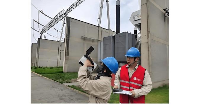
UV imaging technology employs specialized instruments to capture the UV signals generated by discharges. These signals are processed and superimposed onto visible-light images, enabling accurate determination of corona location and intensity, thereby providing a reliable basis for evaluating the overall performance and operational status of electrical equipment. Additionally, UV imaging systems use a UV beam splitter to separate incoming light into two paths, directing one portion to an image intensifier.

Since corona discharges emit UV light primarily in the 230 nm to 405 nm wavelength range—and UV imaging typically operates within a narrow band of 240 nm to 280 nm—the resulting signal is inherently weak. The image intensifier amplifies this faint signal into a visible image, achieving high-resolution visualization under conditions free from solar UV radiation. Furthermore, by integrating a CCD camera and applying special image processing, UV imaging systems can overlay UV and visible-light images, ultimately generating a composite view that clearly displays both the electrical equipment and its associated corona activity.

Power Testing Equipment...jpg

2. Applications of UV Imaging Detection Technology in Equipment Inspection

UV imaging detection technology is widely used in power systems for pollution assessment, insulator discharge detection, transmission line maintenance, and insulation defect identification. The following sections analyze its key applications.

2.1 Pollution Inspection
Pollution inspection forms the foundation of UV imaging applications in power systems. Contaminants on electrical equipment surfaces are often uneven and can trigger discharges under voltage stress. By assessing the degree of conductor contamination and the distribution of pollutants on insulators, personnel can effectively detect and analyze equipment conditions. This information provides a solid basis for designing and implementing effective maintenance and cleaning strategies.

2.2 Insulator Discharge Detection
Insulator discharge detection is a critical application of UV imaging. Surface contamination on insulators can produce UV-visible corona, as can intrinsic insulator degradation. When using UV imaging for detection, personnel should conduct inspections at appropriate sensitivity levels and distances to effectively identify discharge activity. This enables precise location and quantification of degraded insulators, allowing for accurate assessment of their potential impact on system reliability.

Power Testing Equipment..jpg

2.3 Power Line Maintenance
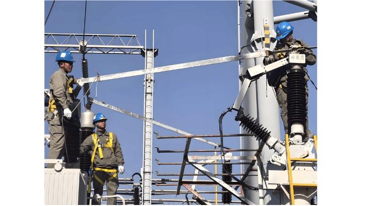
Power line maintenance represents a vital use case for UV imaging. Traditional methods, such as auditory inspection or night-time visual observation of discharges, have significant limitations. Many discharges do not immediately affect equipment operation, making them difficult to detect by sound, while visual methods at night are heavily influenced by distance and environmental conditions. In contrast, practical applications have proven that UV imaging enables comprehensive scanning of substations and transmission lines. It effectively distinguishes between normal and abnormal corona activity, allowing dynamic monitoring, timely identification of anomalies, and informed decision-making for maintenance actions.

2.4 Insulation Defect Detection
Insulation defect detection is another major application. During high-voltage withstand tests, UV imaging allows personnel to observe discharge phenomena in real time. The occurrence of flashovers or arcs indicates poor insulation performance. If corona is observed, its significance must be evaluated in context—considering the equipment’s material, structure, geometry, and service conditions—to conduct a comprehensive assessment of insulation integrity.

3. Research on UV Imaging Technology for Electrical Equipment Inspection

Ongoing research in UV imaging for electrical equipment inspection drives advancements in power system reliability. Key research areas include UV detection calibration for electrical equipment and evaluation of corona discharge consequences.

3.1 UV Detection Calibration for Electrical Equipment
Calibration is a crucial research focus. Standardized calibration methods significantly improve the accuracy of UV imaging and help mitigate the influence of environmental factors such as temperature, humidity, and altitude. However, due to the complexity of UV calibration, extensive research is still required to establish reliable and universally applicable standards.

3.2 Evaluation of Corona Discharge Consequences
Assessing the consequences of corona discharge is an important supporting technology. Environmental conditions can strongly influence corona intensity, making it difficult to directly correlate UV activity with the presence or severity of defects. Therefore, further research is needed to develop robust evaluation models. Nevertheless, effective consequence assessment can greatly enhance the fault detection capability of UV imaging and contribute significantly to improving the reliability of power equipment.

Give a tip and encourage the author!
Recommended
3D Wound-Core Transformer: Future of Power Distribution
Technical Requirements and Development Trends for Distribution Transformers Low losses, especially low no-load losses; highlighting energy-saving performance. Low noise, particularly during no-load operation, to meet environmental protection standards. Fully sealed designto prevent transformer oil from contacting external air, enabling maintenance-free operation. Integrated protection devices within the tank, achieving miniaturization; reducing transformer size for easier on-site installation. C
Echo
10/20/2025
Reduce Downtime with Digital MV Circuit Breakers
Reduce Downtime with Digitized Medium-Voltage Switchgear and Circuit Breakers"Downtime" — it’s a word no facility manager wants to hear, especially when it’s unplanned. Now, thanks to next-generation medium-voltage (MV) circuit breakers and switchgear, you can leverage digital solutions to maximize uptime and system reliability.Modern MV switchgear and circuit breakers are equipped with embedded digital sensors that enable product-level equipment monitoring, providing real-time insights into the
Echo
10/18/2025
One Article to Understand the Contact Separation Stages of a Vacuum Circuit Breaker
Vacuum Circuit Breaker Contact Separation Stages: Arc Initiation, Arc Extinction, and OscillationStage 1: Initial Opening (Arc Initiation Phase, 0–3 mm)Modern theory confirms that the initial contact separation phase (0–3 mm) is critical to the interrupting performance of vacuum circuit breakers. At the beginning of contact separation, the arc current always transitions from a constricted mode to a diffused mode—the faster this transition, the better the interruption performance.Three measures c
Echo
10/16/2025
Advantages & Applications of Low-Voltage Vacuum Circuit Breakers
Low-Voltage Vacuum Circuit Breakers: Advantages, Application, and Technical ChallengesDue to their lower voltage rating, low-voltage vacuum circuit breakers have a smaller contact gap compared to medium-voltage types. Under such small gaps, transverse magnetic field (TMF) technology is superior to axial magnetic field (AMF) for interrupting high short-circuit currents. When interrupting large currents, the vacuum arc tends to concentrate into a constricted arc mode, where localized erosion zones
Echo
10/16/2025
Send inquiry
Download
Get the IEE Business Application
Use the IEE-Business app to find equipment, obtain solutions, connect with experts, and participate in industry collaboration anytime, anywhere—fully supporting the development of your power projects and business.