Relay Protection Basics: Types of Transmission Line Faults and Fundamental Protection Schemes

1. Types of Faults on Power Lines
Phase-to-Phase Faults:
Three-phase short circuit
Two-phase short circuit
Ground Faults:
Single-phase to ground fault
Two-phase to ground fault
Three-phase to ground fault
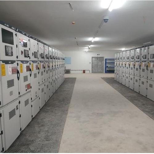
2. Definition of Relay Protection Devices
When an abnormality or fault occurs in a component of a power system, relay protection devices are those that can quickly and selectively isolate the faulty or abnormal component from the system, ensuring the continued normal operation of the remaining healthy equipment.
Examples include: overcurrent protection, distance protection, zero-sequence protection, and high-frequency protection.
Main Protection: Protection that meets the basic requirements for system stability and equipment safety during a short-circuit fault. It operates first to trip the circuit breaker and selectively clears faults on the protected equipment or entire line.
Backup Protection: Protection that removes the fault if the main protection or circuit breaker fails to operate.
Auxiliary Protection: Simple protection added to compensate for limitations in main and backup protection.
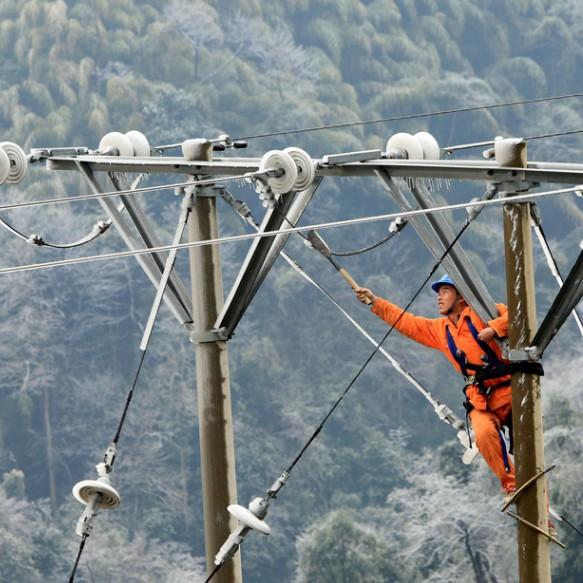
3. Role of Relay Protection in Transmission Lines
During operation, transmission lines may experience faults due to strong winds, ice and snow, lightning strikes, external damage, insulation failure, or pollution flashover. In such cases, the relay protection device can act quickly and selectively, tripping the line circuit breaker (switch).
If the fault is transient, the switch successfully recloses after the fault disappears, restoring safe power supply. If the fault is permanent, the reclosing fails, and the faulty line is rapidly isolated, ensuring uninterrupted power supply to the healthy lines.
4. Overcurrent Protection Devices
Overcurrent protection devices are designed based on the significant increase in current during a line fault. When the fault current reaches the protection setting (pickup current), the device initiates operation. Once the time delay setting is reached, the line circuit breaker trips.
Common types include:
Instantaneous Overcurrent Protection: Simple, reliable, and fast-acting, but only protects a portion (typically 80–85%) of the same line.
Time-Delayed Overcurrent Protection: Operates with a short time delay, protecting the full length of the line and coordinating with the instantaneous protection of the next downstream line.
Overcurrent Protection: Set to avoid maximum load current. It protects the entire length of the line and the full length of the next line, serving as backup protection.
Directional Overcurrent Protection: Adds a power direction element to overcurrent protection. It operates only when the fault power flows from the bus to the line, preventing misoperation during reverse-direction faults.
5. Distance Protection Devices
Distance protection responds to the impedance (or distance) between the fault point and the protection installation point. It has excellent directional characteristics and is widely used on high-voltage ring networks. Three-stage distance protection is commonly employed:
Zone I: Instantaneous operation, protecting 80%–85% of the line length.
Zone II: Protects the entire length of the line and extends into part of the next line (typically Zone I of the adjacent line).
Zone III: Protects the full length of this line and the next line, serving as backup for Zones I and II.
6. Zero-Sequence Current Protection Devices
In directly grounded neutral systems (also known as high-earth-fault-current systems), a single-phase-to-ground fault produces a significant zero-sequence current. Protection devices that use this current are called zero-sequence current protection devices. A three-stage configuration is commonly used:
Stage I: Instantaneous zero-sequence current protection, covering 70%–80% of the line length.
Stage II: Time-delayed zero-sequence current protection, covering the full line length and part of the next line.
Stage III: Zero-sequence overcurrent protection, covering the full line and serving as backup for the next line.
7. High-Frequency Protection Devices
High-frequency protection converts the phase angle (or power direction) of currents at both ends of a line into high-frequency signals, which are transmitted via a high-frequency channel to the opposite end. The system compares the current phase or power direction at both ends.
This protection only responds to faults within the protected line section and does not require coordination with downstream lines. It operates without time delay, enabling rapid clearance of any fault along the protected line.
Based on operating principles, high-frequency protection is classified into:
Blocking Type (Directional Comparison): Compares power direction at both ends.
Phase Comparison Type: Compares current phase angles at both ends.
8. Automatic Reclosing Devices
An automatic reclosing device is one that automatically re-closes the circuit breaker after it has tripped.
Function:
For transient faults, after the fault clears, the device quickly re-closes the breaker, restoring normal power supply.
For permanent faults, the reclosing fails, the breaker trips again, and the faulty line is isolated, ensuring continued power supply to healthy lines.
9. Line Fault Recorder
A device that automatically records the waveforms of current and voltage before and during a line fault, along with the timing and circuit breaker operation status.
By analyzing the recorded waveforms, the fault type can be accurately determined, and the approximate fault location can be calculated. This provides critical data for fault analysis, troubleshooting, and restoration of normal power supply.