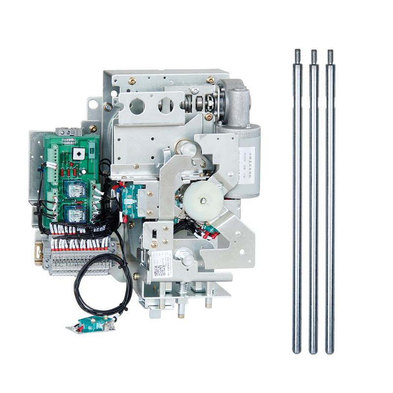
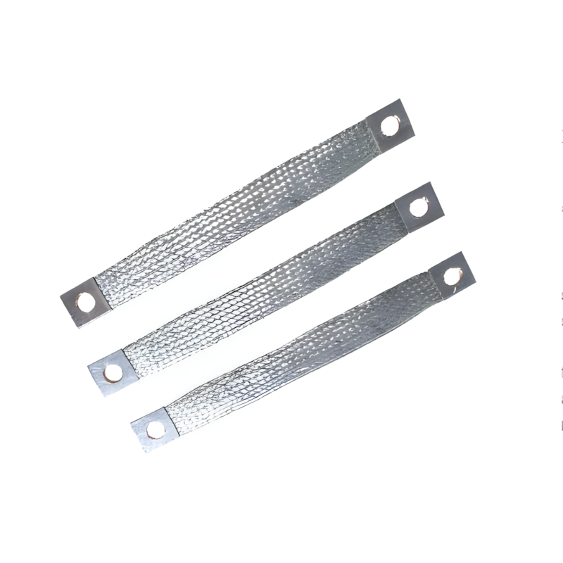
How to Calculate Short Circuit Current of Circuit Breaker

03/25/2024

How To Calculate Short Circuit Current

When there is a short circuit fault in the electrical system, a huge short circuit current flows through the system including the circuit breaker (CB) contacts, unless the fault is cleared by tripping the CB. When the short circuit current flows through the CB, the different current carrying parts of the circuit breaker are subjected to huge mechanical and thermal stresses.

If the conducting parts of the CB do not have sufficient cross-sectional area, there may be a chance of dangerously high temperature rise. This high temperature may affect insulation quality of the CB.

The CB contacts also experience high temperature. The thermal stresses of CB contacts are proportional to I2Rt, where R is the contact resistance, depends upon contact pressure and contact surface condition. I is the rms value of short circuit current and t is duration for which the short circuit current has flown through the contacts.

After initiating fault, the short circuit current stays until the interrupting unit of CB, breaks. Hence, time t is breaking time of the circuit breaker. As this time is very less in scale of mili second, it is assumed that all the heat produced during fault is absorbed by the conductor since there is no sufficient time for convention and radiation of heat.
The temperature rise can be determined by the following formula,

Where, T is the temperature rise per second in degree centigrade.
I is the
current (rms symmetrical) in Ampere.
A is the cross-sectional area of the conductor.
ε is the temperature coefficient of
resistivity of the conductor at 20oC.

As it is known to us, that aluminum above 160oC losses its mechanical strength and becomes soft, it is desired to limit the temperature rise below this temperature. This requirement actually sets the permissible temperature rise during short circuit. This limit can be achieved by controlling CB breaking time and proper designing of conductor dimension.

Short Circuit Force

The electromagnetic force developed between two parallel electric current carrying conductors, is given by the formula,

Where, L is the length of the both conductors in inch.
S is the distance between them in inch.
I is the current carried by each of the
conductors.

It is experimentally proved that, electromagnetic short circuit force is maximum when the value of short circuit current I, is 1.75 times the initial rms value of the symmetrical short circuit current wave.

However, in certain circumstances it is possible that, forces greater than these may develop, such as, for instance in the case of very rigid bars or due to resonance in the case of bars liable to mechanical vibration. Experiments have also shown that the reactions produced in a non resonating structure by an alternating current at the instant of application or removal of the forces may exceed the reactions experienced while the current is flowing.

Thus it is advisable to error on the side of safety and to allow for all contingencies, for which one should take into account the maximum force which could be developed by the initial peak value of the asymmetrical short circuit current. This force may be taken as having a value which is twice of that calculated from the above formula.

The formula is strictly useful for circular cross-sectional conductor. Although L is a finite length of the portions of conductors run parallel to each other, but the formula is only suitable where the total length of each conductor is assumed as infinite.

In practical cases the total length of the conductor is not infinite. It is also considered in mind, that, the flux density near the ends of current carrying conductor is considerably different than its middle portion.

Hence, if we use above formula for short conductor, the force calculated would be much higher than actual.

It is seen that, this error may be eliminated considerably if we use the term,

is stead of L/S in the above formula.
The formula then becomes,

The formula, represented by equation (2), gives error free result when the ratio L/S is greater than 20. When 20 > L/S > 4, formula (3) is suitable for error free result.
If L/S < 4, formula (2) is suitable for error free result. The above formulas are only applicable for circular cross-sectional conductors. But for rectangular cross-sectional conductor, the formula needs to have some correction factor. Say this factor is K. Hence, the above formula ultimately becomes,

Although the effect of shape of cross-section of conductor reduces rapidly if spacing between the conductor increases the value of K is maximum for strip like conductor whose thickness is quite less than its width. K is negligible when shape of cross-section of conductor is perfectly square. K is unity for perfectly circular cross-sectional conductor. This holds true for both standard and remote control circuit breaker.

Statement: Respect the original, good articles worth sharing, if there is infringement please contact delete.

Hello,I'm Wdwiin. A decade of hands-on experience in electrical engineering, specializing in high-voltage systems, smart grids, and renewable energy technologies. Passionate about technical exchange and knowledge sharing, committed to interpreting industry trends with professional insights to empower peers. Connection creates value—let’s explore the boundless possibilities of the electrical world together!

What is the difference between a dielectric and an insulator?
Dielectrics and insulators are distinguished primarily by their applications. One of the main differences is that a dielectric can store electrical energy by becoming polarized in an electric field, whereas an insulator resists the flow of electrons to prevent current conduction. Other key differences between them are outlined in the comparison chart below.Definition of DielectricA dielectric material is a type of insulator that contains few or no free electrons. When subjected to an electric fi
08/30/2025
What losses occur during operation of the transformer? How to reduce losses?
Transformers experience various types of losses during operation, primarily categorized into two main types: copper losses and iron losses.Copper LossesCopper losses, also known as I²R losses, are caused by the electrical resistance of the transformer windings—typically made of copper. As current flows through the windings, energy is dissipated in the form of heat. These losses are proportional to the square of the load current (I²R), meaning they increase significantly with high
Rockwell
08/29/2025
Cable Fault Detection, Testing, Location and Repair
I. Methods for Cable Testing and Inspection:Insulation Resistance Test: Use an insulation resistance tester to measure the insulation resistance value of the cable. A high insulation resistance value indicates good insulation, while a low value may suggest insulation problems requiring further investigation.Voltage Withstand Test: Apply a high-voltage test using a high-voltage tester to verify whether the cable can withstand high voltage under its rated operating conditions. Under normal circums
08/29/2025
Cable Quality Inspection and Cable Detection & Testing
Power cable quality inspection and cable testing are conducted to ensure that the cable's quality and performance meet specified requirements, thereby guaranteeing the safe and stable operation of power systems. Below are some common contents of power cable quality inspection and cable testing:Visual Inspection: Check the cable surface for physical defects such as damage, deformation, or scratches to ensure the cable's exterior is intact.Dimensional Measurement: Measure dimensional parameters su
08/29/2025
Inquiry
Download
IEE-Business is dedicated to serving the personnel in the global power industry.
Join IEE-Business, not only can you discover power equipment and power knowledge, but also canhnd like - minded friends!