
תקלות נפוצות בקווים תלוים
הסיבות הנפוצות ביותר לתקלות בקווים תלוים כוללות:
מאמר קשור: הגנה על טרנספורמטורי כוח והפרעות
מכשירי הגנה לקווים תלוים
הגנה על זרם מוגבר לפי זמן אינה יעילה לקווי העברה בתקרה גבוהה (HV). זה עקב קיום מספר מקורות מתחברים של זרמי תקלות, שעשויים להיות מוגבלים על ידי מגבילי זרמי תקלות. דרישות המפתח עבור סכמות הגנה בקווים תלוים בתקרה גבוהה הן כדלקמן:
כדי לעמוד בדרישות אלו, מכשירי הגנה הבאים בשימוש נפוץ בקווים תלוים בתקרה גבוהה:
הגנה דיפרנציאלית בדרך כלל מתבצעת לקוות תלוים קצרים, בעוד שמגיני מרחק מתאימים יותר לקוות תלוים ארוכים. הסיווג של קווי תלוים כקצרים או ארוכים מבוסס על השוואת האינדוקטיביות, ההתנגדות והקיבוליות של הקו. קו נחשב לקצר כאשר ההתנגדות והקיבוליות שלו זניחות בהשוואה לאינדוקטיביות שלו. הערכה זו מבוצעת לעתים קרובות באמצעות הדיאגרמה π של הקו התלוי.
מספר גורמים משפיעים על עמידות הקו, התגובה הפיזית שלו לתנאי קצר-مدار וזרם טעינת הקו. אלה כוללים את רמת המתח, הבנייה הפיזית של קו ההעברה, סוג וגודל המוליכים, והמרווח בין המוליכים. בנוסף, מספר הנמלים של הקו משפיע על זרימת הזרמים של עומס ותקלות, שהמערכת ההגנה צריכה לקחת בחשבון. קווים מקבילים גם משפיעים על ההפעלה, שכן הקישור הדדי יכול להשפיע על הזרם הקרקעי שנמדד על ידי מתגי הגנה. הימצאות טרנספורמרים מושכים או מכשירי פיצוי ריאקטיביים, כגון בנקים קONDENSATORS or shunt reactors, further influences the selection of the protection system and the settings of protection devices. As a result, a detailed study of the overhead line is necessary to determine the most appropriate protection relays. Generally, a line with a length of up to 80 - 100 km may be considered short, although this can vary depending on the voltage level and network characteristics.
Approximately 90% of overhead line faults are transient in nature. Faults can be categorized as follows:
For such faults, a single - pole - trip may be required, allowing the line to be restored to service immediately after the circuit breakers trip. Consequently, single - pole - trip and auto - reclose schemes are commonly used in circuit breakers associated with overhead transmission lines (usually with a voltage of 220 kV or higher). When the circuit breakers interrupt the fault current, the flashover arc is extinguished, and the ionized air dissipates. Auto - reclosing is usually successful after a delay of just a few cycles. However, when energized work is being performed, the automatic reclosing devices on the lines under work must be set to non - reclosing mode. Circuit breakers used in these applications need to be specifically designed to handle these operations and be immune to pole inconstancy until a definitive trip order is issued.
Differential and Phase Comparison Protection
Differential protection is based on Kirchhoff's current law. In the context of a transmission line, it works by comparing the current entering the line at one terminal with the current leaving the line at the other terminal. Line differential relays at each end of the transmission line exchange data on the line current through a fiber - optic communications link. This link is often established using the Optical Power Ground Wire (OPGW) cable, which is also used for the lightning protection design of the overhead line and contains fiber - optic cables within its structure. Figure 1 illustrates the diagram of the differential protection system.
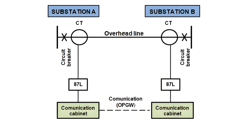
Figure 1 – Overhead Line Differential Protection Diagram
Another protective relaying system for high - voltage (HV) transmission lines, which is grounded in the differential protection principle and is now employed even for long - distance lines, is phase comparison protection.
This system operates by comparing the phase angle between the currents at the two ends of the protected line. In the event of external faults, the current entering the line has the same relative phase angle as the current exiting the line. As a result, the phase comparison relays at each terminal register little to no phase angle difference. Consequently, the protection system remains stable, and no tripping occurs. Conversely, during an internal fault, current flows into the line from both ends, causing a phase angle disparity that the phase comparison relays can detect. Upon identification of this difference, the relays activate to isolate and clear the fault.
In phase comparison schemes, starting relays play a crucial role. These relays initiate the phase comparison process as soon as a fault condition is detected. Their design ensures operation for both internal and external faults, providing comprehensive monitoring.
For the effective functioning of phase comparison protection, a reliable communication channel is indispensable. In modern applications, fiber optic cables integrated within Optical Ground Wire (OPGW) cables have become the preferred choice for establishing this communication link.
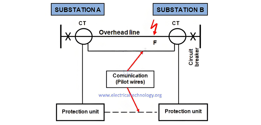
Figure 2 depicts the single - line diagram of the Merz Price voltage balance system, which is utilized for the protection of three - phase lines.
Phase Comparison Protection and Distance Protection
Phase Comparison Protection
Figure 2 – Phase Comparison Protection Diagram
In phase comparison protection, identical current transformers (CTs) are strategically positioned in each phase at both ends of the transmission line. Each pair of CTs, one at each end of the line, is connected in series with a relay. Under normal, non - fault conditions, the secondary voltages generated by these CTs are equal in magnitude but opposite in direction, effectively balancing each other out.
During healthy system operation, the current entering the line at one end precisely matches the current leaving it at the other end. As a result, equal and opposing voltages are induced in the secondaries of the CTs at the two line terminals. This voltage balance ensures that no current flows through the relays, maintaining the stability of the protection system.
However, when a fault occurs at a point such as F on the line, as illustrated in Figure 2, the current distribution is disrupted. Specifically, a significantly larger current will flow through CT1 compared to CT2. This disparity in current causes the secondary voltages of the CTs to become unequal. Consequently, a circulating current is established, flowing through the pilot wires and the relays. In response to this current flow, the circuit breakers at both ends of the line are triggered to open, promptly isolating the faulty line from the rest of the power system.
Also read: Primary and Secondary or Backup protection in a Power System
Distance Protection
Distance protection relies on distance relays, which measure the impedance of a transmission line by analyzing the voltage and current signals applied to them. When a fault occurs on a line, two significant changes take place: the current surges to a much higher level, and the voltage drops precipitously.
Given that the impedance of a transmission line is directly proportional to its length, distance relays are designed to measure the impedance up to a pre - determined point known as the "reach point." These relays, often referred to as impedance relays, calculate impedance using Ohm's law, expressed by the formula Z = U/I, where Z represents impedance, U is voltage, and I is current.
Distance relays are engineered to operate exclusively for faults that occur between the relay's location and the selected reach point. This design feature allows them to effectively distinguish between faults in different line sections. The apparent impedance calculated by the relay is then compared with the pre - set reach point impedance. If the measured impedance is lower than the reach point impedance, it is inferred that a fault exists on the line between the relay and the reach point. When the calculated impedance falls within the reach setting of the relay, the relay activates, initiating the protective action.
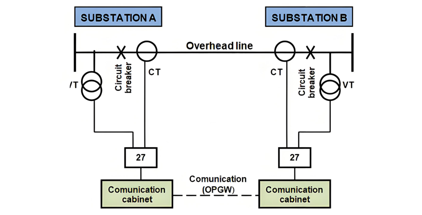
To ensure comprehensive protection, distance protection systems are installed at both ends of the transmission line, and a communication link is established between these endpoints, as depicted in Figure 3. This communication enables coordinated operation of the relays at each end, enhancing the overall effectiveness of the protection scheme.
Distance Relay Performance and Characteristics
Figure 3 – Overhead Line Distance Protection Diagram
The performance of distance relays is primarily evaluated based on two key parameters: reach accuracy and operating time.
Reach Accuracy
Reach accuracy involves comparing the actual ohmic reach of a distance relay under real - world, practical conditions with its pre - set ohmic value. This metric is significantly influenced by the voltage level applied to the relay during fault conditions. A lower or distorted voltage can lead to inaccuracies in the measured impedance, affecting the relay's ability to correctly identify the location of a fault within its designated reach. Additionally, the impedance - measuring techniques utilized in specific relay designs play a crucial role. Different algorithms and hardware configurations can yield varying levels of precision, thereby impacting the overall reach accuracy of the relay.
Operating Time
The operating time of a distance relay is a variable quantity that depends on multiple factors. Fault current magnitude has a direct effect; higher fault currents can sometimes cause faster operation, while lower currents might result in longer response times. The position of the fault relative to the relay's setting also matters. Faults closer to the source or within a certain proximity to the relay might trigger a quicker response compared to those further away. Moreover, the point on the voltage wave at which the fault occurs can introduce variability in the operating time.
Certain measuring signal transient errors, which are associated with the specific measuring techniques employed in a relay's design, can further complicate matters. For instance, errors generated by Capacitor Voltage Transformers (CVT) or saturating Current Transformers (CT) can significantly delay the relay's operation, especially for faults occurring near the reach point. These transient errors can distort the voltage and current signals, leading to misinterpretation of the impedance and a subsequent delay in the relay's activation.
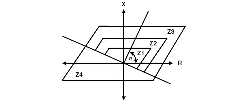
Characteristics of Distance Relays
The characteristics of distance relays, often referred to as the protection shape, are graphically represented as a function of the line's resistance (R) and impedance (X) on an R/X or admittance diagram. Two of the most typical shapes are the circular (mho characteristic) and the quadrilateral. These characteristic shapes are illustrated in Figures 10 and 11, respectively. Each shape has its own advantages and is designed to optimize the relay's performance under different electrical system conditions, providing a reliable means of distinguishing between normal operating conditions and actual faults within the protected line section.
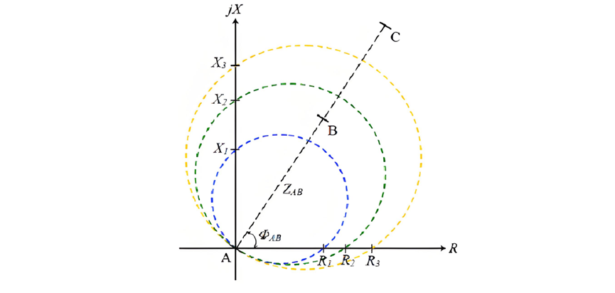
Figure 4 – Mho characteristic
Distance Relay Characteristics, Reach Settings, and Reclosing
Figure 5 – Quadrilateral Characteristic
The mho impedance element earns its name from its characteristic appearance on an admittance diagram, where it manifests as a straight line. However, polygonal impedance characteristics, such as the quadrilateral shape, have gained significant popularity. These characteristics offer remarkable flexibility in covering fault impedances for both phase and earth faults. This adaptability has made them the preferred choice for most modern distance relays.
Distance relays can be configured with up to five distinct zones, some of which are set to measure impedance in the reverse direction. These reverse - measuring zones serve as backup protection for bus bars. Each zone is associated with a specific actuation time for the relay, allowing for a nuanced and coordinated response to faults occurring at different locations within the protected electrical network.
When distance relays are installed on both ends of a transmission line, their response times to a fault vary depending on the distance of the fault point (F) from each end of the line. For instance, consider an overhead line connecting Substations A and B. The distance relay situated in the substation closest to the fault point F will detect the fault first, and the corresponding circuit breaker will trip before the one at the other substation.
To prevent a short - circuit fault from continuing to receive power from the opposite end of the line until the relevant distance protection activates, a communication link between the protection relays is essential. Typically, this communication is established via optical fiber cables integrated within Optical Ground Wire (OPGW) cables. This setup enables the simultaneous tripping of both circuit breakers, ensuring rapid and effective isolation of the faulty section.
It is impractical to program an impedance relay to precisely measure the impedance of the line all the way to the breaker at the remote end. This is due to inherent errors and inaccuracies in components such as current transformers (CTs), voltage transformers (VTs), relays themselves, as well as in the calculations of line impedance. To account for these uncertainties, the relay's reach is set to measure an impedance value less than the total impedance corresponding to the full length of the line. For example, setting Zone 1 to cover up to 85% of the line's impedance is a common and safe practice. The remaining 15 - 20% serves as a safety margin, effectively preventing Zone 1 protection from over - reaching the protected line due to measurement errors and inaccuracies. Without this margin, there would be a risk of losing the ability to discriminate between faults on adjacent line sections, particularly when dealing with fast - acting protection schemes.
Careful calibration of the reach settings and tripping times for each measurement zone is crucial for achieving proper coordination among distance relays across the power system. This meticulous adjustment ensures that faults are cleared in the correct sequence, minimizing disruptions and maintaining the stability of the electrical grid.
Related Read: Introduction to Harmonics – Effect of Harmonics on Power System
Reclosing
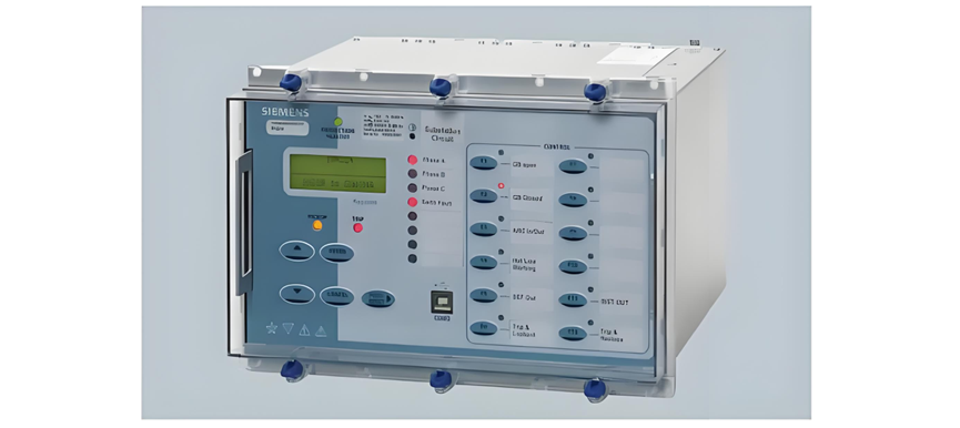
As discussed in Section 4.2, the majority of faults on overhead lines are asymmetric and transient in nature. Auto - reclosing, a critical functionality in power systems, is executed by an auto - recloser relay. This relay is triggered by the protection devices of the overhead line, as illustrated in Figure 6.
Auto - Reclosing in Power Systems
Figure 6 – Auto - Recloser Relay
The decision to reclose an electrical line is influenced by numerous factors. Input and guidance from planning and operational teams are essential for determining the most suitable reclosing practices tailored to the specific requirements of a utility company and its region. Key considerations for transmission - level reclosing include:
Major Considerations
Key Parameters of Auto - Reclose Schemes
The most critical parameters of an auto - reclose scheme are:
These parameters are influenced by several factors:
Reclosing Strategies
Reclosing can be implemented in different ways:
The choice between these strategies requires a careful assessment of the benefits and potential consequences, weighing the associated risks for each specific application.
Reclosing practices on non - critical lines, as identified by planning groups, can vary widely depending on the protection philosophy and the equipment deployed. Moreover, there is significant variation in reclosing practices among different utilities, influenced by factors such as voltage levels and the type of line (e.g., overhead vs. underground).
Some companies adopt a policy of auto - reclosing for all faults, except when there is a loss of communication. Others reclose when the fault clearance time is sufficiently fast, regardless of the fault configuration.
System Stability and Reclosing
System stability is a decisive factor in determining whether high - speed auto - reclosing should be attempted. The feasibility of reclosing depends on the strength of the transmission system:


