What is Induction Voltage Regulators?

Edwiin
04/06/2025

What is Induction Voltage Regulators?

Definition: An induction voltage regulator is a kind of electrical machine. Its output voltage can be adjusted, ranging from zero up to a specific maximum value. This range depends on the turn ratio between the primary and secondary windings. The primary winding is linked to the circuit that requires voltage regulation, while the secondary winding is connected in series with the same
 

Types of Induction Voltage Regulators

Induction voltage regulators are primarily categorized into two types: the single - phase induction voltage regulator and the three - phase induction voltage regulator.

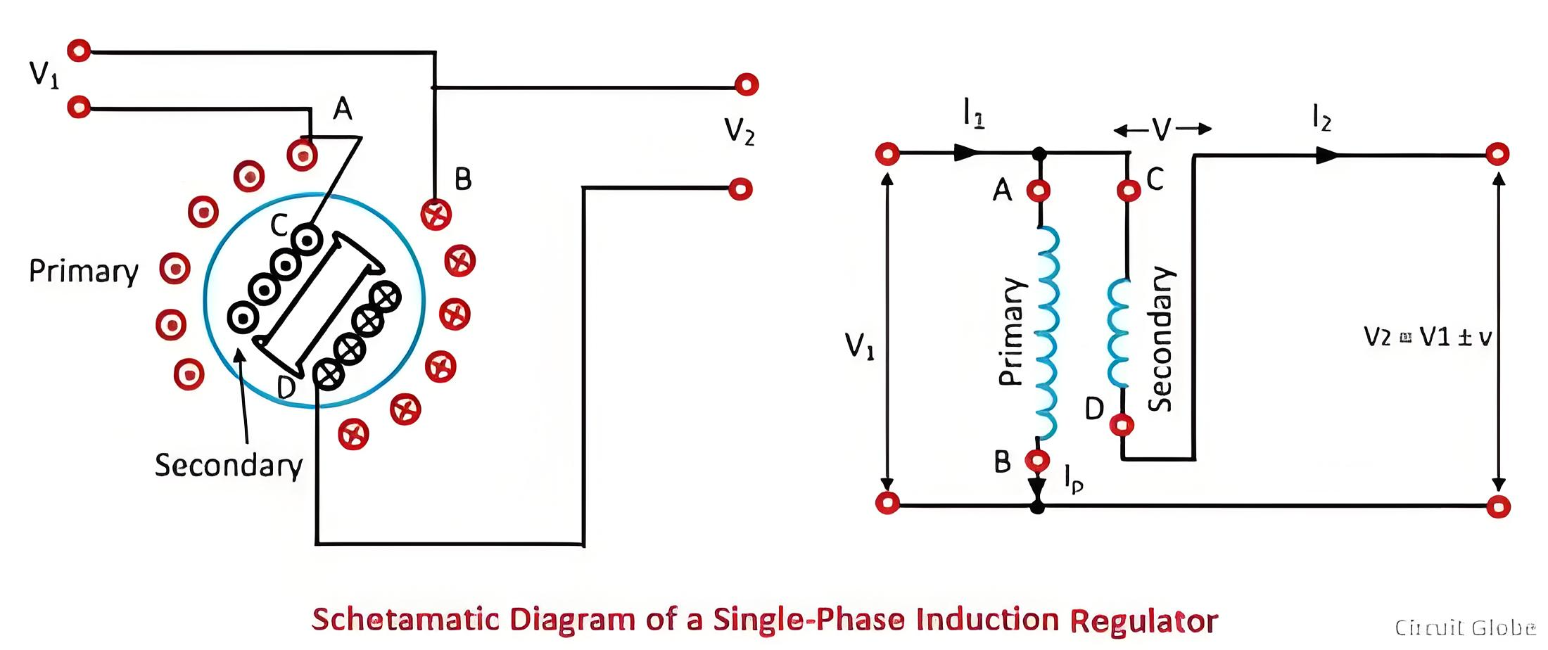
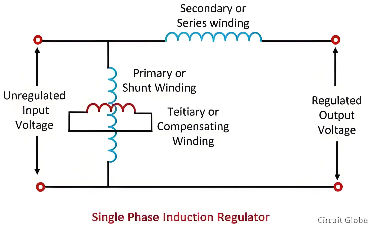
Single - phase Induction Voltage Regulator

The schematic diagram of a single - phase induction voltage regulator is presented in the figure below. The primary winding is connected across the single - phase power supply, and the secondary winding is connected in series with the outgoing lines.

In this system, an alternating magnetic flux is induced. When the axes of the two windings align, all of the magnetic flux from the primary winding links with the secondary winding. As a result, the maximum voltage is induced in the secondary winding.
 
 
When the rotor is rotated by 90º, no part of the primary flux is linked with the secondary windings; thus, no flux is present in the secondary windings. If the rotor continues to rotate beyond this point, the direction of the induced electromotive force (emf) in the secondary becomes negative. Consequently, the regulator either adds to or subtracts from the circuit voltage, depending on the relative orientation of the two windings within the regulator.

The single - phase voltage regulator does not introduce any phase shift. The primary windings are installed in slots on the surface of the laminated cylindrical core. Since they carry relatively small currents, they have a small conductor cross - sectional area. The rotor of the regulator incorporates compensating windings, also referred to as tertiary windings.

The magnetic axis of the compensating windings is always oriented 90º away from that of the primary windings. This configuration serves to counteract the detrimental series reactance effect of the secondary windings. The secondary windings, which are connected in series with the outgoing line, are located in the stator slots because of their larger conductor area requirements.

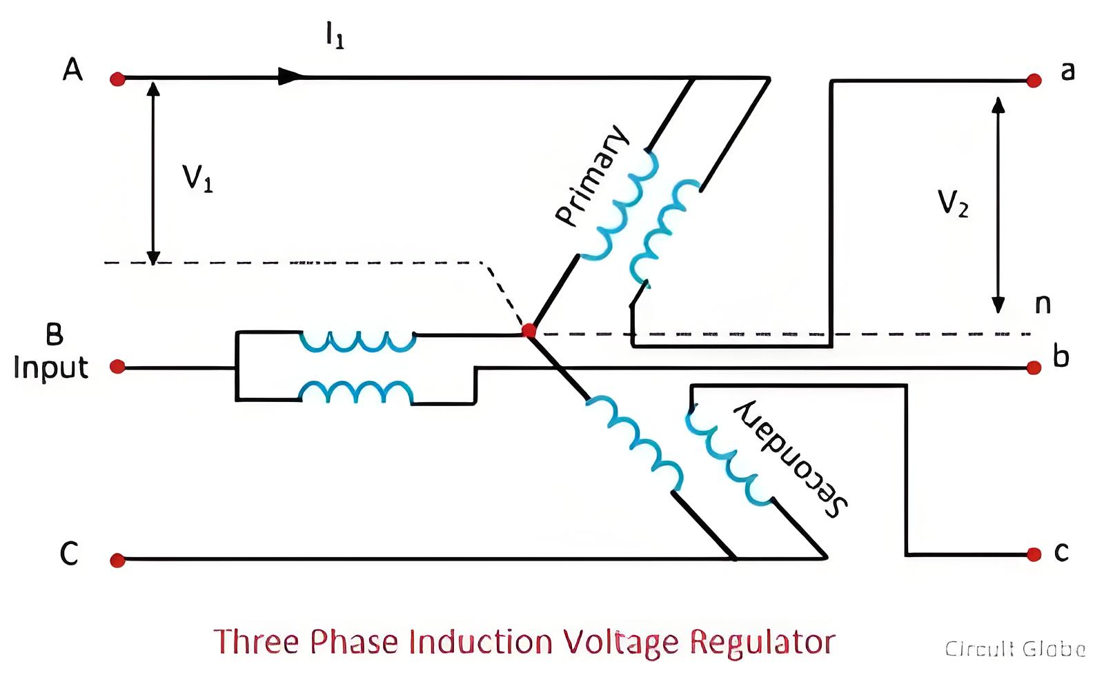
Three - Phase Induction Voltage Regulator

Three - phase induction voltage regulators feature three primary windings and three secondary windings, which are spaced 120º apart from one another. The primary windings are placed in the slots of a laminated rotor core and are connected across a three - phase AC power supply. The secondary windings are housed in the slots of a laminated stator core and are connected in series with the load.
The regulator does not necessitate separate primary and compensating windings. This is because each secondary winding of the regulator is magnetically linked to one or more primary windings within the regulator. In this type of regulator, a rotating magnetic field of consistent magnitude is generated. As a result, the voltage induced in the secondary winding also has a constant magnitude. However, the phases of the regulator change in accordance with the variation in the rotor's position relative to the stator.
The phasor diagram of the induction regulator is depicted in the figure above. Here, (V1) represents the supply voltage, (Vr) is the voltage induced in the secondary, and (V2) denotes the output voltage per phase. The output voltage is derived as the phasor sum of the supply voltage and the induced voltage for any rotor displacement angle θ.

Consequently, the locus of the resultant is a circle. This circle is drawn with its center located on the tip of the supply voltage vector and has a radius equal to (Vr). The maximum output voltage is achieved when the induced voltage is in - phase with the supply voltage. Conversely, the minimum output voltage is obtained when the induced voltage is in anti - phase with the supply voltage.

The complete phasor diagram for the three - phase case is shown in the figure below. The terminals labeled AB, and C are the input terminals, while ab, and c are the output terminals of the induction regulator. The supply and the output line voltages are in - phase only at the maximum boost and minimum buck positions. For all other positions, there exists a phase displacement between the supply line voltage and the output voltage.
 
 
Edwiin

Analysis of the Principle of Second - harmonic Restraint for Overcurrent Protection of Distribution Automation Switches
Substance of Second - harmonic Restraint in Overcurrent ProtectionThe substance of second - harmonic restraint in overcurrent protection is to use the second - harmonic component to judge whether the current is a fault current or an excitation inrush current. When the percentage of the second - harmonic component to the fundamental - wave component is greater than a certain value, it is judged to be caused by the excitation inrush current, and the overcurrent protection is blocked.Therefore, the
Leon
07/18/2025
What are the typical connection methods for 35kV distribution lines?
Typical Wiring Diagram of 35kV Line Radial π ConnectionWhen a 35kV line adopts a radial power grid structure, a single - side power supply or a double - side power supply radial type can be used according to the situation of the power supply points, and a loop - out interval is reserved at the end of the line.Typical Wiring Diagram of 35kV Line Radial T - ConnectionFor double - radial lines, it is advisable to select a double - side power supply. When the power supply points do not meet the r
Leon
07/18/2025
Why are the ground fault point and the accident point not at the same location?
Fault Transfer VoltageIn low - voltage distribution systems, there is a type of personal electric shock accident where the accident occurrence point and the system fault point are not at the same location. This kind of accident occurs because after a ground fault happens elsewhere, the generated fault voltage is conducted to the metal casings of other equipment through the PE wire or PEN wire. When the fault voltage on the metal casing of the equipment is higher than the human - body safe voltag
Leon
07/18/2025
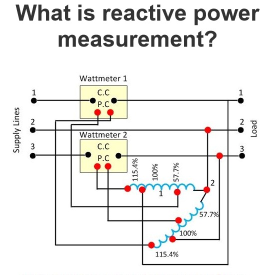
What is reactive power measurement?
The power which exists in the circuit when the voltage and current are out of phase to each other, such type of power is known as the reactive power. The formula measures the reactive power in the circuitReactive Power Measurement & VarmetersReactive power measurement is critical as it indicates circuit power loss: low reactive power worsens load power factor, increasing system losses. Varmeters (volt-ampere reactive meters) measure reactive power and are categorized by circuit phases:Single
Edwiin
07/17/2025
Inquiry
Download
IEE-Business is dedicated to serving the personnel in the global power industry.
Join IEE-Business, not only can you discover power equipment and power knowledge, but also canhnd like - minded friends!