Construction of a Transformer

Transformer Construction and Key Components
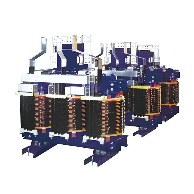
A transformer primarily comprises a magnetic circuit, electric circuit, dielectric circuit, tank, and auxiliary components. Its core elements are the primary/secondary windings and a steel core, with the core constructed from silicon steel to form a continuous magnetic path. Transformer cores are typically laminated to minimize eddy current losses.
Magnetic Circuit
The magnetic circuit consists of the core and yoke, providing a pathway for magnetic flux. It features a laminated steel core with two insulated coils (primary and secondary), both isolated from each other and the core.
Core Material: Laminated steel or silicon steel sheets, chosen for their low hysteresis losses at standard flux densities.
Structural Terms:
Limbs: Vertical sections where coils are wound.
Yoke: Horizontal sections connecting limbs to complete the magnetic path.
Electric Circuit
The electric circuit comprises primary and secondary windings, typically made of copper:
Conductor Types:
Rectangular cross-section conductors: Used for low-voltage windings and high-voltage windings in large transformers.
Circular cross-section conductors: Employed in high-voltage windings of small transformers.
Transformers are classified by core construction and winding placement into:
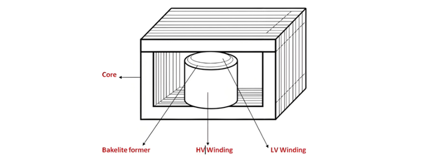
Core-Type Transformer Construction
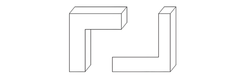
In the core-type transformer design, the core is formed by laminating rectangular frame structures. The laminations are typically cut into L-shaped strips, as illustrated in the figure below. To minimize magnetic reluctance at the lamination joints, alternate layers are arranged in a staggered pattern, eliminating continuous joint lines and ensuring a smooth magnetic path.
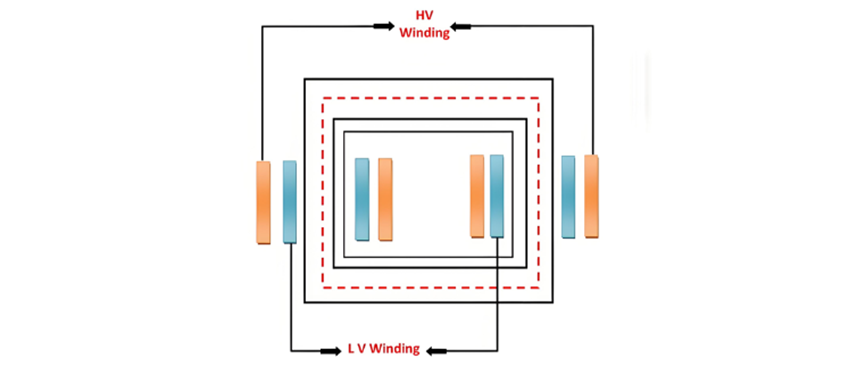
Primary and secondary windings are interleaved to minimize leakage flux, with half of each winding arranged either side-by-side or concentrically on each core limb. During placement, Bakelite former insulation is inserted between the core and low-voltage (LV) winding, between LV and high-voltage (HV) windings, between coils and the yoke, and between the HV limb and yoke, as depicted in the figure below. The LV winding is positioned closer to the core to reduce insulation requirements, optimizing both material efficiency and electrical safety.
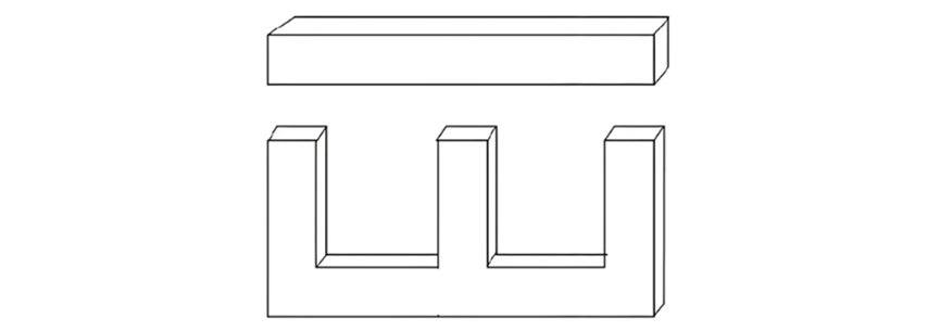
Shell-Type Transformer Construction
In a shell-type transformer, individual laminations are cut into long E- and I-shaped strips (as shown in the figure below), forming two magnetic circuits with a three-limb core. The central limb, twice the width of the outer limbs, carries the total magnetic flux, while each outer limb conducts half the flux, optimizing magnetic efficiency and minimizing leakage.
Shell-Type Transformer Design and Transformer Components
Shell-Type Transformer Winding and Core Structure
Leakage flux in shell-type transformers is minimized by subdividing windings, reducing reactance. Primary and secondary windings are co-located on the central limb: the low-voltage (LV) winding sits adjacent to the core, with the high-voltage (HV) winding wrapped around it. To cut lamination costs, windings are pre-formed into cylindrical shapes, with core laminations inserted afterward.
Dielectric Circuit
The dielectric circuit comprises insulating materials separating conductive parts. Core laminations (0.35–0.5mm thick for 50 Hz systems) are coated with varnish or an oxide layer to minimize eddy current losses and ensure electrical isolation between layers.
Tanks and Accessories
Conservator
A cylindrical tank mounted on the transformer’s main tank roof, the conservator acts as an insulating oil reservoir. It accommodates oil expansion during full-load operation, preventing pressure buildup as temperature fluctuates.
Breather
Functioning as the transformer’s "heart," the breather regulates air intake during oil expansion/contraction. Silica gel inside absorbs moisture from incoming air, preserving oil quality: fresh blue gel turns pink as it saturates, with dry gel capable of lowering air dew points below -40°C.
Explosion Vent
A thin aluminum pipe installed at both transformer ends, the explosion vent relieves excessive internal pressure caused by sudden temperature surges, safeguarding the transformer from damage.
Radiator
Detachable radiator units cool transformer oil via natural convection: heated oil rises into the radiator, cools, and returns to the tank through valves, maintaining a continuous cooling cycle.
Bushings
Insulating devices allowing electrical conductors to pass through the tank, bushings withstand high voltage fields. Small transformers use solid porcelain bushings, while large units employ oil-filled condenser-type bushings. Moisture ingress is a primary failure mode, detectable via power factor tests (e.g., Doble Power Factor Test) that monitor insulation degradation.
Recommended