Types of 3 Phase Induction Motor

Encyclopedia
08/15/2024

Three phase induction motor definition

A three-phase induction motor is an asynchronous motor that operates at a different speed than a synchronous one and uses a three-phase power supply.

c4c326fdb0ae064a2860d69e9431de98.jpeg

Stator

The stator is the stationary part of the motor that receives a three-phase power supply to generate a rotating magnetic field.

Major component composition

Stator frame

The stator frame is the exterior of the three-phase induction motor. It supports the stator core and the field windings, providing protection and mechanical strength for the internal parts. The frame is made of die cast or prefabricated steel and must be strong and rigid to maintain a small gap between the rotor and the stator and prevent unbalanced magnetic pulling.

Stator core

The main function of the stator core is to carry AC magnetic flux. It is laminated to reduce eddy current losses, with a thickness of 0.4 to 0.5 mm per lamination. These sheets are stamped together to form the stator core, which is housed in the stator frame. The lamination is made of silicon steel to help reduce lag losses.

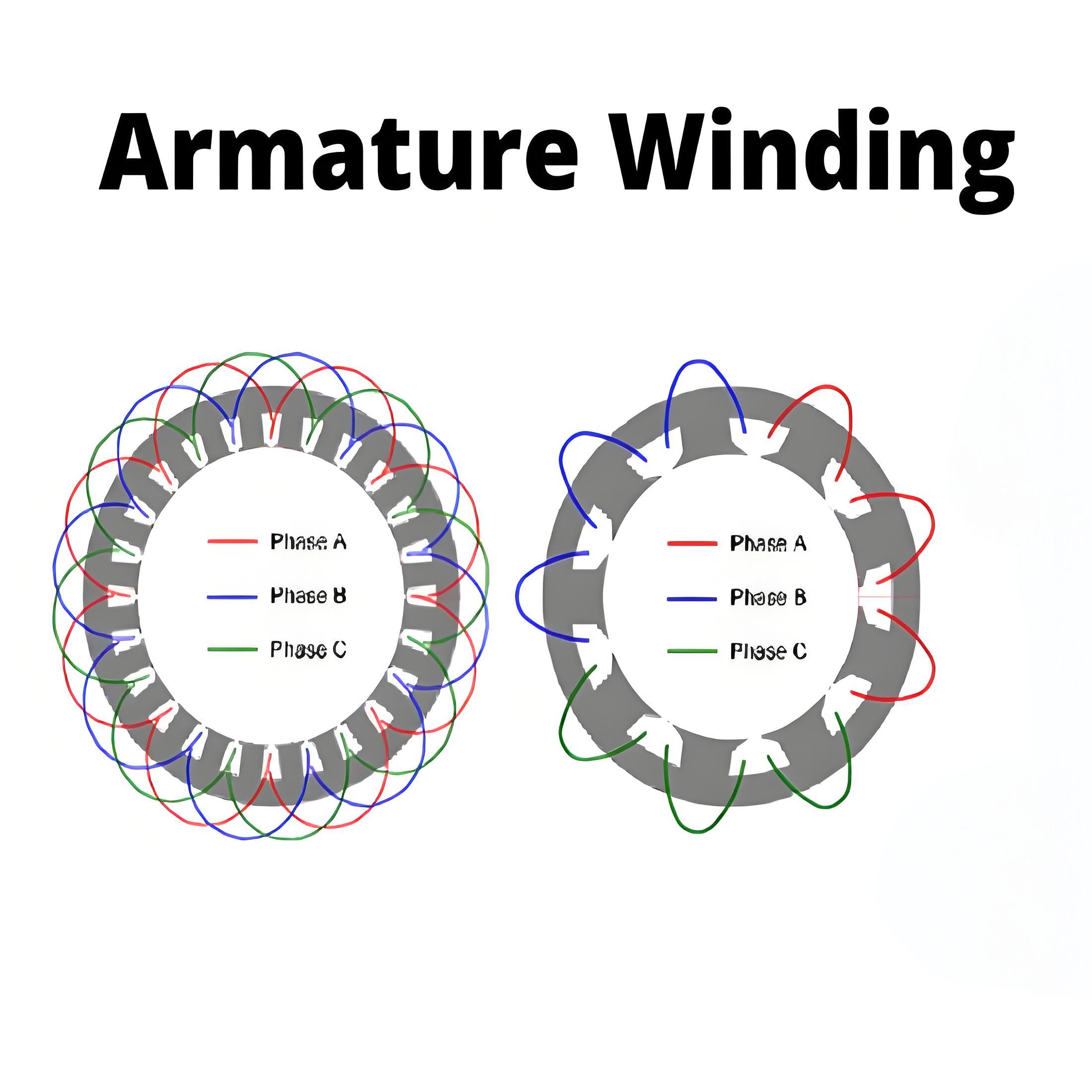
Stator winding or field winding

The slot outside the stator core of the three-phase induction motor bears the three-phase winding. The three-phase winding is supplied by a three-phase AC power supply. The three phases of the winding are connected in a star or triangle shape, depending on the type of starting method used.

The squirrel cage motor is mostly started by the star triangle stator, so the stator of the squirrel cage motor is connected by a triangle. The slip ring three-phase induction motor is started by inserting a resistor, so the stator windings can be connected in a star or triangle shape. The winding winding on the stator of the three-phase induction motor is also called the field winding, when the winding is excited by the three-phase AC power supply, it will produce a rotating magnetic field.

Rotor

The rotor is attached to a mechanical load and rotates within the stator's magnetic field.

Type of rotor

  • Squirrel cage rotor

  • Slip ring rotor

Encyclopedia

The Electricity Encyclopedia is dedicated to accelerating the dissemination and application of electricity knowledge and adding impetus to the development and innovation of the electricity industry.

What is Induction Motor Drives ?
What is Induction Motor Drives ?Induction Motor Drives DefinitionInduction motor drives are systems that control the performance of induction motors by adjusting frequency and voltage to manage speed, torque, and position.Starting Methods Star delta starter Auto-transformers starter Reactor starter Saturable reactor starter Part winding starter AC voltage controller starter Rotor resistance starter is used for starting of wound rotor motor.Braking TypesRegenerative braking.plugging or reverse vo
Encyclopedia
08/22/2024
Induction Motor Braking
Braking of Induction MotorInduction motors are used in many applications. Speed control of induction motors is difficult, which initially limited their use, favoring DC motors instead. However, the invention of induction motor drives highlighted their advantages over DC motors. Braking is crucial for controlling motors, and induction motors can be braked using various methods, including: Regenerative braking of induction motor Plugging Braking of induction motorDynamic braking of induction motor
Encyclopedia
08/21/2024
Armature Winding
Armature Winding
Armature winding definitionThe armature winding in an alternator is the arrangement of coils to generate electricity and is essential to its operation.Type of armature windingSingle-phase armature windingSingle-phase armature windings can be centralized or distributed.Centralized armature windingWhen the number of slots on the armature equals the number of poles in the machine, the central winding is used. This winding type provides maximum output voltage, but is not always fully sinusoidal. The
Encyclopedia
08/17/2024
Power Derivation  in Synchronous Motors
Power Derivation in Synchronous Motors
Power Flow in Inductive CircuitsPower flow through an inductive impedance involves voltage sources and a load with a resistor and inductor.Phasor DiagramsPhasor diagrams visually represent voltages and currents in a circuit, helping to understand power conditions.Power Equation of Synchronous GeneratorThe power equation of a synchronous generator relates the voltage, current, and phase angles to determine power output.Maximum Power Output ConditionsMaximum power output in alternators and synchro
Encyclopedia
08/17/2024
Inquiry
Download
IEE-Business is dedicated to serving the personnel in the global power industry.
Join IEE-Business, not only can you discover power equipment and power knowledge, but also canhnd like - minded friends!