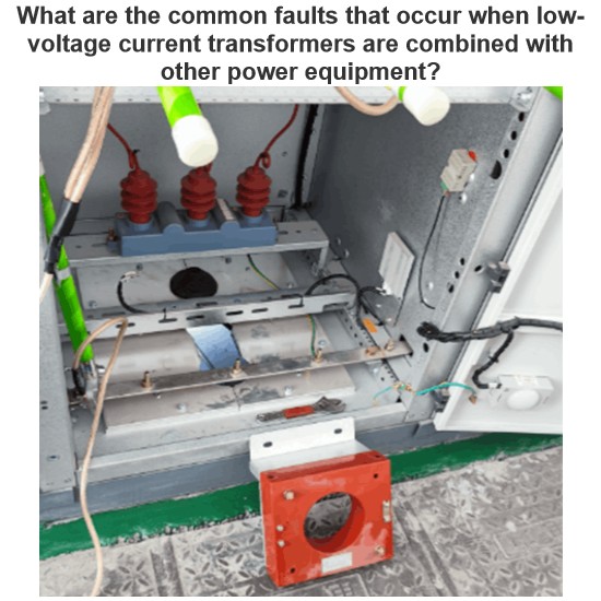
What are the common faults of low-voltage voltage transformers?

Open - Circuit Fault on the Secondary Side
Open - circuit in the secondary side is a typical fault of low - voltage voltage transformers, showing abnormal voltmeter readings (zero/fluctuation), faulty power meters, buzzing noises, and core overheating. When open - circuited, the secondary voltage spikes (no secondary current to balance the primary EMF), causing core saturation, flux distortion, and potential overheating/damage.
Causes include loose terminals, poor contact, or human error. In low - voltage systems, the secondary side connects parallel to meters/protection devices (high impedance, near no - load). A break/poor contact forms an open circuit—e.g., rusted 10kV substation terminals caused open - circuit, voltmeter errors, and protection misoperation.
To fix: First, disable misoperation - prone protections. Check joints/terminals (measure secondary resistance with a multimeter). Repair open - circuit points safely. Temporarily short - circuit the secondary at test terminals (not for long - term use).
Insulation Damage Fault
Insulation damage is common, causing high - voltage fuse melting, internal discharge, overheating, or fire. Caused by moisture, rust, dust, or mechanical damage (degrading insulation materials like epoxy resin, silicon steel, or paper).
Epoxy resin’s water absorption rises sharply in high humidity/temperature (95% RH, 65℃), dropping volume resistivity from 1.57×10¹⁵Ω·cm to 5.21×10¹⁴Ω·cm. Dust and vibration accelerate aging.
Example: A 10kV substation’s voltage transformer failed due to water ingress (poor sealing), reducing insulation resistance and melting the high - voltage fuse.
Prevention: Regular insulation tests (>1MΩ, 2500V megohmmeter for 10kV PTs). Keep equipment clean, ensure single - point grounding. For damp transformers: mild cases use hot oil circulation; severe cases need vacuum drying or insulation replacement.
Excessive Error Fault
Excessive error causes mismatched meter readings, metering deviations, and protection misjudgments. Per JJG314 - 2010, errors must stay within limits for 25%–100% rated secondary load. Out - of - range loads (too high/low) cause errors.
Causes: Overloaded secondary, excessive conductor voltage drop, poor contacts, or harsh environments. E.g., long/small - cross - section 10kV secondary wires caused >0.5% metering errors.
Fix: Check secondary connections (ensure good contact). Measure wire length/cross - section; replace/shorten wires if needed. Adjust errors (replace if adjustment fails).
Mechanical Damage Fault
Mechanical damage (winding deformation, loose cores, broken shells) comes from improper transport, installation, or vibration. It harms accuracy and causes partial discharge/insulation issues—e.g., 10kV transformer installation vibration loosened the core, causing noise and errors.
Prevention: Use shock - absorbing packaging (honeycomb cardboard + polyurethane foam) during transport (limit component displacement to <1mm). Install per specs, check structure regularly.
Multi - point Grounding Fault of the Secondary Circuit
Multi - point grounding causes neutral voltage shifts, protection misjudgments. Low - voltage systems require single - point grounding; multi - point grounding creates circulating currents.
Causes: Poor installation, damaged wires, or bad contacts. E.g., 10kV substation B/C phase auxiliary windings grounded together caused over - current, fuse melting, and protection misoperation.
Fix: Identify and remove extra ground points (ensure one ground). Check connections. Test resistance between UN and the protection panel’s ground bar (≈0Ω indicates multi - point grounding).
Hey there! I'm an electrical engineer specializing in Failure and Maintenance. I've dedicated my career to ensuring the seamless operation of electrical systems. I excel at diagnosing complex electrical failures, from malfunctioning industrial motors to glitchy power distribution networks. Using state - of - the - art diagnostic tools and my in - depth knowledge, I pinpoint issues quickly. On this platform, I'm eager to share my insights, exchange ideas, and collaborate with fellow experts. Let's work together to enhance the reliability of electrical setups.