Kadadda Risuka na Gwargwadon Dukkana a 12 kV Air-Insulated RMUs Ta Hanyar Grading Shield Design

Wannan makaranta ta shafi shi ne ya zama da primary isolation break wata nau'in 12kV air-insulated ring main unit (RMU) a matsayin abin da ake bincike, tana nuna cikakken sadarwa da kula da tsarin electric field da ke kan ita, tana bayyana yadda ake gano hanyoyin insulation performance a wannan wurin, da kuma ya yi amfani da structural optimization don in haɗe discharge risk da kuma in sauki hanyoyin insulation, don haka za su iya ba da takardun da za su iya amfani da shi a kan abubuwan design daban-daban.
1 Tsari na Air-Insulated Ring Main Unit
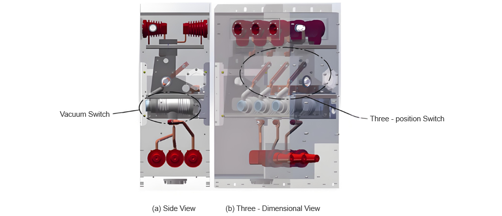
An nuna model na tsari na air-insulated RMU da ake bincike a cikin wannan makarantanci a Figure 1. An samun sabbin circuit da configuration mai kombinoci da vacuum switch da three-position switch, an juye three-position switch a busbar side—wanda three-position switch yake cika a tsakiyar RMU, sai dai vacuum switch yake cika a karamin RMU a solid-sealed pole structure. Saboda vacuum switch yake faɗi a cikin pole, karfin ita ce epoxy resin, wanda yake da hanyoyin insulation da suka fiye da hankali, kuma yana tabbatar da hanyoyin insulation.
Akwai kuma connection busbar a sealing point na solid-sealed pole, wanda an yi chamfered edges da arc-shaped design, da kuma silicone rubber sealing, wadanda suke haɗe partial discharge issues a wannan wurin. Insulation clearances da ke bayan busbars da ground suka faɗi a cikin standards na insulation da suka sanar da su, kuma suka tabbatar da regulatory requirements.
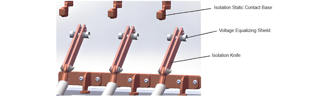
Isolation blade na three-position switch tana amfani da air as insulating medium. A cikin ita, akwai metal parts kamar pins, springs, disc springs, da circlips don in sauki contact pressure bayan isolation contacts. Amma, saboda shapes na abubuwan metal parts su, distribution na electric field zai iya zama da tsawon tsawo, wanda yake iya haɓaka partial discharge da kuma breakdown risks, wadanda suke juye insulation performance a wannan wurin.
Saboda haka, electrical design na wannan tsari yana da muhimmanci sosai. Daɗi requirements na product design, isolation break yana buƙaci a taka rated short-time power-frequency withstand voltage na 50kV, da minimum designed electrical clearance na 100mm. Saboda tsawon tsawo na isolation blade, an samu grading shields a duk biyu na blade don in sauki uniformity na electric field da kuma in haɗe partial discharge. Model na tsari na three-position switch an nuna a Figure 2. Wannan makaranta tana yi electric field simulation analysis a wannan isolation break.
2 Simulation Analysis
An amfani da finite element software don in yi electric field simulation a ring main unit, tana bayyana distribution na electric field strength a isolation break a cikin specified 50 kV rated short-time power-frequency withstand voltage. An samu duɗɗukan electrostatic field simulation cases:
Case 1: Busbar side (isolation fixed contact side) yana ciki a low potential (0 V), kuma line side (isolation blade tip side) yana ciki a high potential (50 kV).
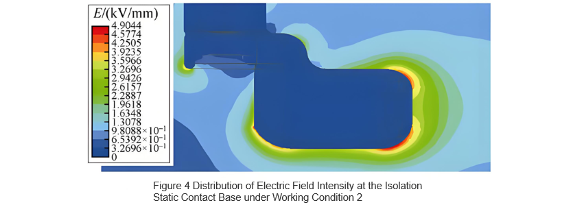
Case 2: Busbar side (isolation fixed contact side) yana ciki a high potential (50 kV), kuma line side (isolation blade tip side) yana ciki a low potential (0 V).
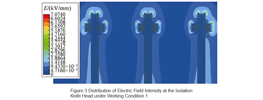
Distribution na electric field a location na maximum electric field strength don duk case su an samu ta hanyar simulation. Distribution na electric field strength a isolation blade tip a Case 1 an nuna a Figure 3, kuma distribution a isolation fixed contact a Case 2 an nuna a Figure 4. A Case 1, maximum electric field strength yana faruwar a tsakiyar grading shield, yana ciki 7.07 kV/mm; a Case 2, maximum yana faruwar a chamfered edge na isolation fixed contact, yana ciki 4.90 kV/mm.
Typical critical breakdown electric field strength na air yana ciki 3 kV/mm. Kamar yadda ake nuna a Figures 3 da 4, hakan da electric field strength a duk areas na isolation break yana ciki ɗaya da 3 kV/mm—babu iya yin breakdown—amman lokutan yana ciki ɗaya da wannan limit, wanda yake iya haɓaka partial discharge. Idan air yana ƙarfi daga dry zuwa humid conditions, hanyoyin insulation suke ƙara [10], wanda yake ƙara critical uniform breakdown field strength ɗaya da 3 kV/mm. Duk da haka, tsawon tsawo na electric field distribution yana ƙara critical breakdown strength na air, wanda yake yin likelihood da risk na breakdown. Don in haɗe impact na environmental factors na air insulation medium da kuma in sauki field uniformity, wannan research tana bayyana degree na electric field uniformity da withstand voltage level across isolation break, don haka za su iya ba da takardun da za su iya amfani da shi don in sauki hanyoyin insulation na break.
3 Air Insulation Characteristics
3.1 Determination of Electric Field Non-Uniformity Coefficient
A cikin practice, babu electric field da yake perfect uniform; duk electric fields suna da tsawon tsawo. Ta hanyar electric field non-uniformity coefficient f, electric fields suka ci gaba da duɗɗukan types: idan f ≤ 4, field yana cikin slightly non-uniform; idan f > 4, yana cikin highly non-uniform. Non-uniformity coefficient f an define shi a cikin f = Eₘₐₓ/Eₐᵥ, inda Eₘₐₓ shine maximum local electric field strength, an samu shi daga peak value a results na simulation, da Eₐᵥ shine average electric field strength, an samu shi a cikin applied voltage divided by minimum electrical clearance.
Daga Figure 3, Eₘₐₓ = 7.07 kV/mm da Eₐᵥ = 0.5 kV/mm. Saboda haka, electric field non-uniformity coefficient a isolation break yana ciki f = 14.14 > 4, wanda yake nuna highly non-uniform electric field. A lokutan da suka da highly non-uniform fields, stable partial discharge zai faru, da kuma ɗaya da tsawon tsawo, yana iya faru partial discharge da ƙarfin ita. Don 12 kV ring main unit, total partial discharge quantity na entire cabinet yana buƙaci a taka 20 pC [5,11]. Saboda haka, in ƙara electric field non-uniformity coefficient yana taimaka wajen ƙara partial discharge level.
3.2 Determination of Air Withstand Voltage
Electric field non-uniformity coefficient tana taimaka wajen withstand voltage na dry air. Idan field yana cikin slightly non-uniform, withstand voltage yana ciki:
indidi U yana nufin withstand voltage; d yana nufin minimum electrical clearance between electrodes; k yana nufin reliability factor, typically ranging from 1.2 to 1.5 based on experience; and E₀ yana nufin dielectric breakdown electric field strength na gas. A cikin practice, this breakdown field strength depends on the specific configuration of the two electrodes, and the air breakdown strength varies with different electrode structures and clearance distances. For the purpose of comparative analysis, this paper assumes E₀ = 3 kV/mm. As indicated by Equation (1), increasing the minimum electrical clearance d and reducing the electric field non-uniformity coefficient f can both enhance the withstand voltage of the air insulation medium.
Idan a kaɗai da highly non-uniform electric field, for electrodes with a minimum electrical clearance within the 100 mm range, the withstand voltage is calculated as follows:
In the formula, U50%(d) represents the 50% breakdown voltage of an electrode under a specific electrical clearance d during lightning impulse tests. In highly non-uniform electric fields, there is significant dispersion in breakdown voltages and longer discharge time lags, making the breakdown voltage highly unstable. In practical engineering applications, U50%(d) is determined by conducting multiple lightning impulse tests and identifying the applied voltage at which there is a 50% probability of breakdown. This value is closely related to the product's structure and the uniformity of the electric field. It is established that a lower electric field non-uniformity coefficient results in less dispersion in breakdown voltage, higher breakdown voltage, and consequently, higher withstand voltage. Therefore, reducing the electric field non-uniformity coefficient is beneficial for enhancing the withstand voltage of the isolation break.
4 Structural Optimization
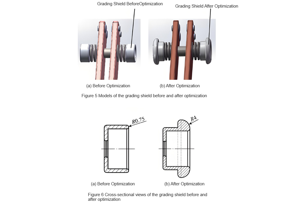
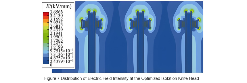
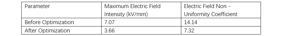
To improve the uniformity of the electric field around the isolation blade tip and reduce the electric field non-uniformity coefficient, optimization of the grading shield structure was carried out. Models of the grading shield before and after optimization are shown in Figure 5, while cross-sectional views are provided in Figure 6. As can be seen from Figure 6, compared to the pre-optimization design, the optimized grading shield features a thicker end with rounded corners, increasing the corner radius from 0.75 mm to 4 mm. This enhancement increases the curvature radius, promoting more uniform distribution of the electric field. The electric field strength distribution around the optimized isolation blade tip is illustrated in Figure 7. From this figure, it is evident that the maximum electric field strength has been reduced to 3.66 kV/mm, approximately half of its original value, indicating a notable improvement.
According to the aforementioned formula f=Emax/Eav, the non-uniformity coefficient of the electric field after optimization is 7.32, which is approximately halved compared to before optimization.
This indicates a significant improvement in the uniformity of the electric field around the isolation blade tip, demonstrating that the structural optimization was effective. A comparison of the data before and after the grading shield optimization is shown in Table 1. As can be seen from Table 1, the optimized grading shield structure indeed reduces the risk of breakdown discharge between the isolation breaks. However, the electric field between the isolation breaks remains highly non-uniform, meaning its withstand voltage is still determined by U50%(d). The extent of improvement in withstand voltage can be further confirmed through on-site testing.
This translation maintains the technical details and context provided in the original text, ensuring clarity and accuracy for an English-speaking audience.
5 Experimental Verification
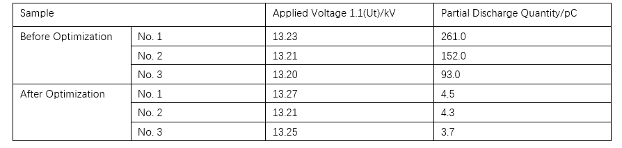
To validate the effectiveness of the simulation analysis, partial discharge tests were conducted on a 12 kV air-insulated ring main unit. Three prototype units (No. 1 to No. 3) were prepared. Partial discharge tests were first performed with the original (pre-optimization) grading shields installed on the isolation blades of all three units. Subsequently, the optimized grading shields were installed, and the tests were repeated. The resulting partial discharge data are presented in Table 2.
As shown in the table, the partial discharge levels before optimization all exceeded 20 pC, while those after optimization were reduced to below 4.5 pC. This indicates that the optimized grading shield structure effectively enhances the insulation performance of the ring main unit and confirms the validity of the preceding simulation and analysis.
6 Conclusion
Based on the electric field analysis of the isolation break in a 12 kV air-insulated ring main unit, the following conclusions are drawn:
Since the insulation capability of air is inferior to that of SF₆, improving electric field distribution is essential to enhance the insulation performance when air is used as the insulating medium in three-position switches of ring main units.
Due to the structural complexity of moving components (isolation blades) in three-position switches of air-insulated ring main units, the electric field strength distribution at certain locations can become highly non-uniform. To reduce this non-uniformity, grading shields can be added on both sides of the isolation blade to shield the high-field regions near the blade's connecting parts, thereby shifting the location of peak field strength to the ends of the grading shields. In this study, increasing the curvature radius at the shield's end from 0.75 mm to 4 mm reduced both the maximum local electric field strength and the electric field non-uniformity coefficient to approximately half of their original values, achieving the desired optimization effect.
The uniformity of electric field distribution, or the electric field non-uniformity coefficient, significantly influences partial and breakdown discharges. Highly non-uniform fields tend to produce stable partial discharge (corona discharge). In both slightly and highly non-uniform fields, a higher non-uniformity coefficient results in lower withstand voltage between the electrodes.
Tambayar Da Yawanci


