Mitigating Discharge Risks in 12 kV Air-Insulated RMUs Using Grading Shield Design

This paper takes the primary isolation break of a certain type of 12kV air-insulated ring main unit (RMU) as the research object, analyzing the electric field distribution and uniformity around it, evaluating the insulation performance at this location, and reducing discharge risk while enhancing insulation performance through structural optimization, thereby providing a reference for the insulation design of similar products.
1 Structure of the Air-Insulated Ring Main Unit
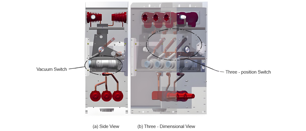
The three-dimensional structural model of the air-insulated RMU studied in this paper is shown in Figure 1. The main circuit adopts a configuration combining a vacuum switch with a three-position switch, arranged with the three-position switch on the busbar side—i.e., the three-position switch is located at the upper part of the RMU, while the vacuum switch is mounted at the lower part in a solid-sealed pole structure. Since the vacuum switch is encapsulated within the pole, its exterior is insulated with epoxy resin, which has significantly better insulation properties than air, thus meeting insulation requirements.
Additionally, the connection busbar at the sealing point of the solid-sealed pole employs chamfered edges and arc-shaped design, combined with silicone rubber sealing, effectively mitigating partial discharge issues in this area. The insulation clearances between busbars and to ground are designed according to relevant insulation standards and satisfy regulatory requirements.
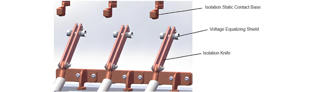
The isolation blade of the three-position switch relies on air as the insulating medium. As a movable connecting component, its structure includes metal parts such as pins, springs, disc springs, and circlips to increase contact pressure between the isolation contacts. However, due to the complex shapes of these metal parts, the electric field distribution can become highly non-uniform, leading to partial discharge and potential breakdown risks, which adversely affect the insulation performance at this location.
Therefore, the electrical design of this structure is particularly critical. According to product design requirements, the isolation break must withstand a rated short-time power-frequency withstand voltage of 50kV, with a minimum designed electrical clearance of 100mm. Given the complexity of the isolation blade structure, grading shields are added on both sides of the blade to improve electric field uniformity and reduce partial discharge. The three-dimensional model of the three-position switch is shown in Figure 2. This paper conducts electric field simulation analysis on this isolation break.
2 Simulation Analysis
Finite element software was used to perform electric field simulation on the ring main unit, analyzing the electric field strength distribution at the isolation break under the specified 50 kV rated short-time power-frequency withstand voltage. Two electrostatic field simulation cases were considered:
Case 1: The busbar side (isolation fixed contact side) is at low potential (0 V), and the line side (isolation blade tip side) is at high potential (50 kV).
Case 2: The busbar side (isolation fixed contact side) is at high potential (50 kV), and the line side (isolation blade tip side) is at low potential (0 V).
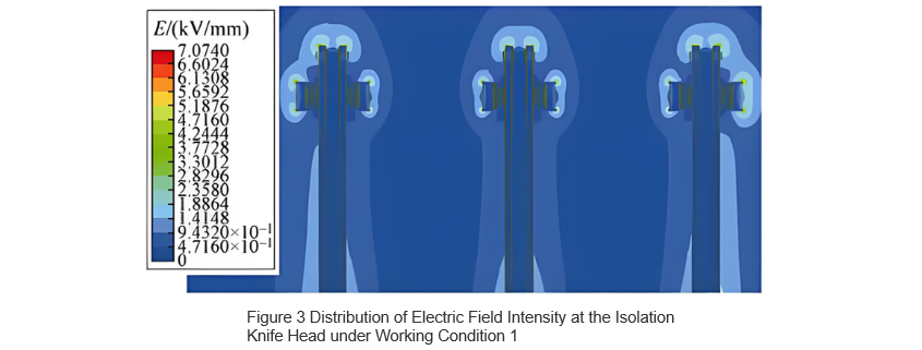
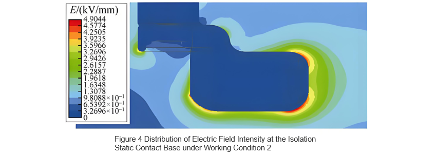
The electric field distribution at the location of maximum electric field strength for both cases was obtained through simulation. The electric field strength distribution at the isolation blade tip under Case 1 is shown in Figure 3, and the distribution at the isolation fixed contact under Case 2 is shown in Figure 4. In Case 1, the maximum electric field strength occurs at the end of the grading shield, reaching 7.07 kV/mm; in Case 2, the maximum occurs at the chamfered edge of the isolation fixed contact, with a value of 4.90 kV/mm.
The typical critical breakdown electric field strength for air is 3 kV/mm. As shown in Figures 3 and 4, while the electric field strength in most areas of the isolation break is below 3 kV/mm—insufficient to cause breakdown—localized regions exceed this threshold, leading to partial discharge. When air changes from dry to humid conditions, its insulation capability decreases [10], lowering the critical uniform breakdown field strength below 3 kV/mm. Additionally, highly non-uniform electric field distribution further reduces the critical breakdown strength of air, increasing the likelihood and risk of breakdown. To mitigate the impact of external environmental factors on the air insulation medium and improve field uniformity, this study evaluates the degree of electric field uniformity and the withstand voltage level across the isolation break, serving as a basis for enhancing the insulation capability of the break.
3 Air Insulation Characteristics
3.1 Determination of Electric Field Non-Uniformity Coefficient
In practice, a perfectly uniform electric field does not exist; all electric fields are inherently non-uniform. Based on the electric field non-uniformity coefficient f, electric fields are classified into two types: when f ≤ 4, the field is considered slightly non-uniform; when f > 4, it is considered highly non-uniform. The non-uniformity coefficient f is defined as f = Eₘₐₓ/Eₐᵥ, where Eₘₐₓ is the maximum local electric field strength, obtained from the peak value in the simulation results, and Eₐᵥ is the average electric field strength, calculated as the applied voltage divided by the minimum electrical clearance.
From Figure 3, Eₘₐₓ = 7.07 kV/mm and Eₐᵥ = 0.5 kV/mm. Therefore, the electric field non-uniformity coefficient at the isolation break is f = 14.14 > 4, indicating a highly non-uniform electric field. In regions with highly non-uniform fields, stable partial discharge can occur, and the higher the degree of non-uniformity, the more pronounced the partial discharge and the greater the discharge magnitude. For a 12 kV ring main unit, the total partial discharge quantity of the entire cabinet is required to be less than 20 pC [5,11]. Hence, reducing the electric field non-uniformity coefficient helps in decreasing the partial discharge level.
3.2 Determination of Air Withstand Voltage
The electric field non-uniformity coefficient affects the withstand voltage of dry air. When the field is slightly non-uniform, the withstand voltage is:
where U denotes the withstand voltage; d represents the minimum electrical clearance between electrodes; k is a reliability factor, typically ranging from 1.2 to 1.5 based on experience; and E₀ refers to the dielectric breakdown electric field strength of the gas. In practice, this breakdown field strength depends on the specific configuration of the two electrodes, and the air breakdown strength varies with different electrode structures and clearance distances. For the purpose of comparative analysis, this paper assumes E₀ = 3 kV/mm. As indicated by Equation (1), increasing the minimum electrical clearance d and reducing the electric field non-uniformity coefficient f can both enhance the withstand voltage of the air insulation medium.
When dealing with a highly non-uniform electric field, for electrodes with a minimum electrical clearance within the 100 mm range, the withstand voltage is calculated as follows:
In the formula, U50%(d) represents the 50% breakdown voltage of an electrode under a specific electrical clearance d during lightning impulse tests. In highly non-uniform electric fields, there is significant dispersion in breakdown voltages and longer discharge time lags, making the breakdown voltage highly unstable. In practical engineering applications, U50%(d) is determined by conducting multiple lightning impulse tests and identifying the applied voltage at which there is a 50% probability of breakdown. This value is closely related to the product's structure and the uniformity of the electric field. It is established that a lower electric field non-uniformity coefficient results in less dispersion in breakdown voltage, higher breakdown voltage, and consequently, higher withstand voltage. Therefore, reducing the electric field non-uniformity coefficient is beneficial for enhancing the withstand voltage of the isolation break.
4 Structural Optimization
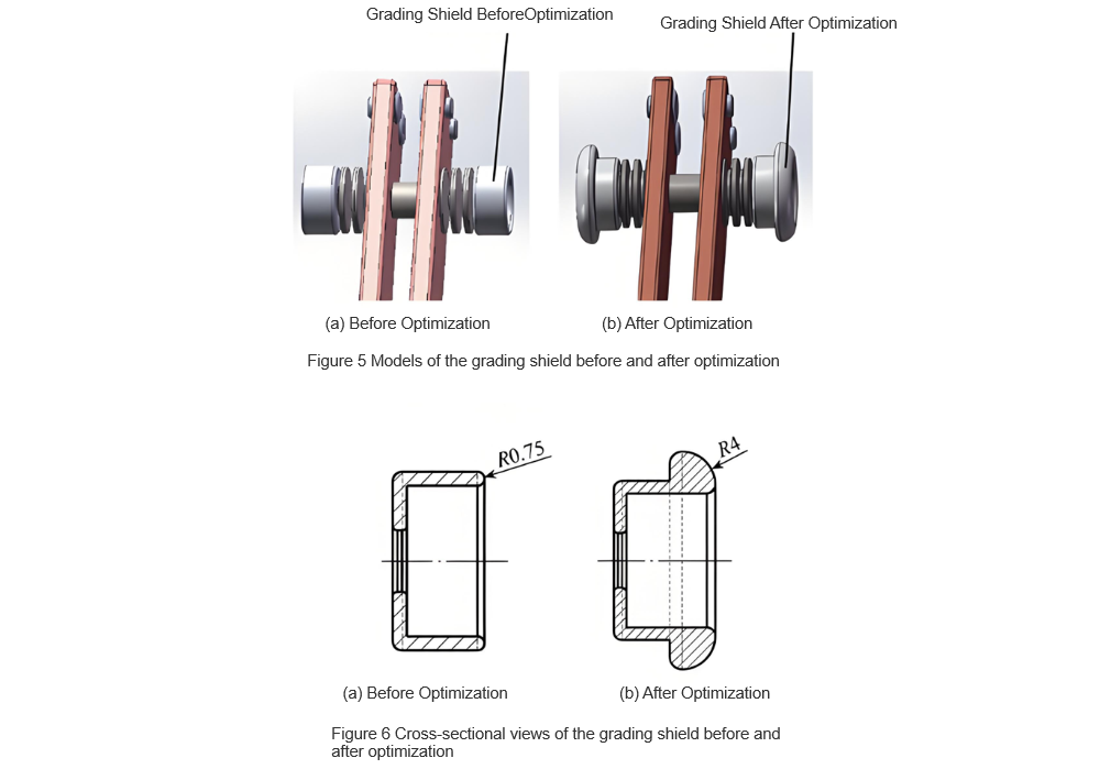
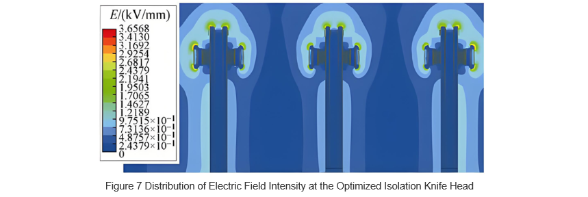
To improve the uniformity of the electric field around the isolation blade tip and reduce the electric field non-uniformity coefficient, optimization of the grading shield structure was carried out . Models of the grading shield before and after optimization are shown in Figure 5, while cross-sectional views are provided in Figure 6. As can be seen from Figure 6, compared to the pre-optimization design, the optimized grading shield features a thicker end with rounded corners, increasing the corner radius from 0.75 mm to 4 mm. This enhancement increases the curvature radius, promoting more uniform distribution of the electric field. The electric field strength distribution around the optimized isolation blade tip is illustrated in Figure 7. From this figure, it is evident that the maximum electric field strength has been reduced to 3.66 kV/mm, approximately half of its original value, indicating a notable improvement.
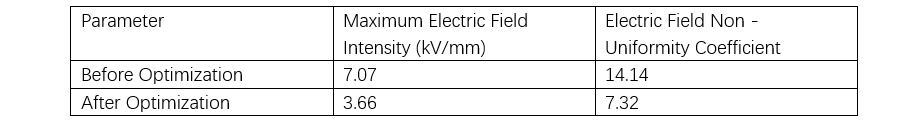
According to the aforementioned formula f=Emax/Eav, the non-uniformity coefficient of the electric field after optimization is 7.32, which is approximately halved compared to before optimization.
This indicates a significant improvement in the uniformity of the electric field around the isolation blade tip, demonstrating that the structural optimization was effective. A comparison of the data before and after the grading shield optimization is shown in Table 1. As can be seen from Table 1, the optimized grading shield structure indeed reduces the risk of breakdown discharge between the isolation breaks. However, the electric field between the isolation breaks remains highly non-uniform, meaning its withstand voltage is still determined by U50%(d). The extent of improvement in withstand voltage can be further confirmed through on-site testing.
This translation maintains the technical details and context provided in the original text, ensuring clarity and accuracy for an English-speaking audience.
5 Experimental Verification
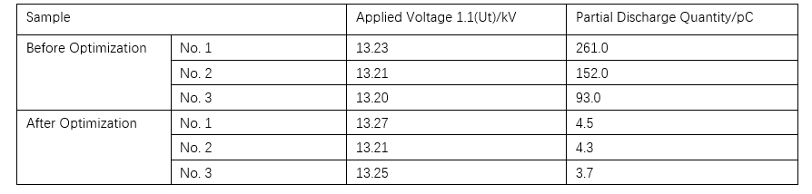
To validate the effectiveness of the simulation analysis, partial discharge tests were conducted on a 12 kV air-insulated ring main unit. Three prototype units (No. 1 to No. 3) were prepared. Partial discharge tests were first performed with the original (pre-optimization) grading shields installed on the isolation blades of all three units. Subsequently, the optimized grading shields were installed, and the tests were repeated. The resulting partial discharge data are presented in Table 2.
As shown in the table, the partial discharge levels before optimization all exceeded 20 pC, while those after optimization were reduced to below 4.5 pC. This indicates that the optimized grading shield structure effectively enhances the insulation performance of the ring main unit and confirms the validity of the preceding simulation and analysis.
6 Conclusion
Based on the electric field analysis of the isolation break in a 12 kV air-insulated ring main unit, the following conclusions are drawn:
Since the insulation capability of air is inferior to that of SF₆, improving electric field distribution is essential to enhance the insulation performance when air is used as the insulating medium in three-position switches of ring main units.
Due to the structural complexity of moving components (isolation blades) in three-position switches of air-insulated ring main units, the electric field strength distribution at certain locations can become highly non-uniform. To reduce this non-uniformity, grading shields can be added on both sides of the isolation blade to shield the high-field regions near the blade's connecting parts, thereby shifting the location of peak field strength to the ends of the grading shields. In this study, increasing the curvature radius at the shield's end from 0.75 mm to 4 mm reduced both the maximum local electric field strength and the electric field non-uniformity coefficient to approximately half of their original values, achieving the desired optimization effect.
The uniformity of electric field distribution, or the electric field non-uniformity coefficient, significantly influences partial and breakdown discharges. Highly non-uniform fields tend to produce stable partial discharge (corona discharge). In both slightly and highly non-uniform fields, a higher non-uniformity coefficient results in lower withstand voltage between the electrodes.
Recommended


