
1 Introduction
To meet the rapidly growing demand for electric energy, power generation, transmission, and distribution systems must develop accordingly. One of the critical issues arising from this development is the rapid increase in short-circuit currents. The rise in short-circuit currents leads to several hazards:
Currently, three main solutions are available to mitigate these effects:
Replacing circuit breakers with higher interrupting capacity is a costly solution and may not be feasible in certain cases. Moreover, protection systems exhibit delays in fault detection based on relay specifications. Circuit breaker operation and arc extinction are not instantaneous, typically requiring 3–5 cycles to fully clear a fault. Consequently, fault currents usually cannot be interrupted within the first 2–8 cycles after a fault occurs. During this period, very high currents flow through series devices in the fault path, and even this brief duration can be destructive, especially during the first cycle when the DC component of the fault current is particularly high.
Bus splitting and reduced system interconnectivity can be considered as alternatives to address this issue. However, they introduce other operational challenges, such as reduced transmission capacity, altered power flow, and increased losses. The need for FCLs arises from the necessity to protect costly and vulnerable equipment. Generally, all proposed FCL strategies are based on inserting high impedance into the series path during a fault, differing only in implementation. The desired characteristics of an ideal FCL are typically:
2 Reliability of Fault Current Limiters
The application of FCLs in substations is generally motivated by two main reasons:
There are various types of FCLs, among which resonant-type and superconducting FCLs are more prominent.
A. Resonant-Type FCLs
Numerous configurations for resonant-type FCLs have been proposed. They are generally classified as series resonant-type and parallel resonant-type FCLs. Resonant-type FCLs possess several favorable characteristics for fault limitation, including:
However, resonant-type FCLs typically consist of multiple components, and the overall reliability depends on the correct operation of each component. Additionally, some resonant-type FCLs require an external triggering device, meaning extra components are needed to sense the short circuit and initiate triggering. This increases system complexity and reduces reliability. Therefore, self-triggered FCLs are evidently more reliable.
B. Superconducting FCLs
Compared to resonant-type FCLs, superconducting FCLs require fewer components and are self-triggered. The fault current limiting strategy is simple and based on the natural behavior of superconducting materials. Superconductivity exists only at very low temperatures, so superconducting FCLs require additional cooling equipment, increasing investment costs. The concept proposed in this paper is limited to evaluating the impact of FCL application on substation reliability.
3 Failure Modes of FCLs
Like other components in high-voltage substations, FCLs exhibit different failure modes that should be considered when assessing the reliability of transmission substations incorporating FCLs. This section compares the failure rates of different types of FCLs.
There is a fundamental relationship between the reliability of a complete system and the number of its subsystems, all of which must operate correctly to achieve the desired overall function.
Clearly, FCLs requiring a triggering system (externally triggered FCLs) have higher failure rates. In general, any FCL involving triggering or commutation involves sequential operations of multiple switching devices, requiring precise synchronization and coordination, significantly increasing complexity compared to conventional circuit breakers.
In resonant-type FCLs (both externally and self-triggered), fixed failure modes may arise due to variations in resonant element characteristics caused by changes in operating conditions such as temperature, or operation under non-rated conditions.
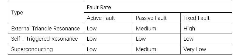
Superconducting FCLs only exhibit such failure modes under excessive cooling, which rarely occurs. Thus, it can be said that superconducting FCLs essentially do not have this failure mode. In most cases, superconducting FCLs can be designed with predictable parameters and withstand thousands of activation and recovery cycles. Furthermore, using smaller FCLs instead of larger ones can improve both reliability and current-limiting capability. Table 1 briefly compares the occurrence rates of different failure modes across various FCL types.
4 Practical Application
A sample substation shown in Fig. 1 is used to evaluate the impact of implementing FCLs on substation reliability. It is well known that during maintenance, using bus-sectioning circuit breakers to manage protection schemes and enhance the flexibility of substation configurations is common practice. When the fault current level in a substation exceeds the interrupting capacity of the circuit breakers, replacing the bus-sectioning breaker with an FCL becomes a viable solution. Indeed, Inter-Bus FCL is one of the most common applications of FCLs.
Assume that all loads connected to the 330 kV bus are identical. The reliability assessment focuses on Load 1 at the left 330 kV bus and Load 5 at the right 330 kV bus. Load reliability is evaluated using the following indices: (1) Load loss probability (%); (2) Annual outage time (U). The 330 kV bus is assumed to be fully reliable. To avoid unnecessary calculations, failure modes involving the simultaneous failure of more than three components are not considered. Since the occurrence rate of such failure modes is very low, this assumption does not introduce significant error.
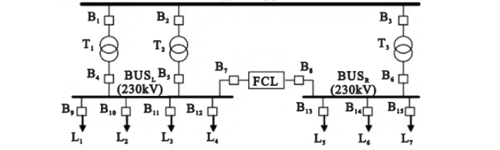
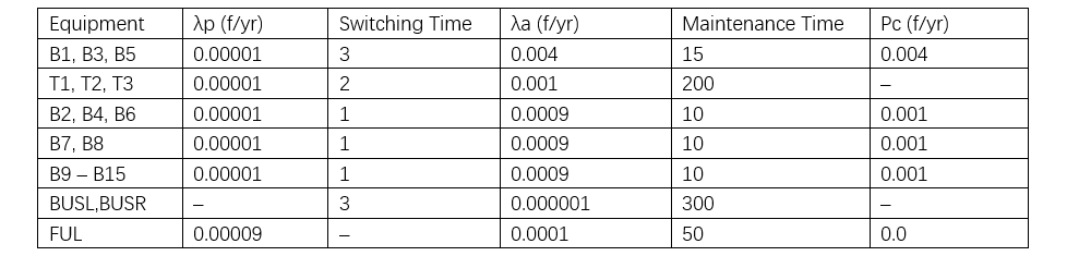
Table 2 shows the failure rates and repair times of the components. For the initial analysis, we start by calculating the reliability indices associated with the left 330 kV bus. To make an informed and comprehensive comparison, theoretically, we should calculate the reliability indices for all load points from L1 to L7. However, given that these loads are similar and connected to the same bus, they will have similar failure modes. Therefore, we only need to calculate the reliability indices for Load Point 1 (L1) on the left bus and Load Point 5 (L5) on the right bus.
As mentioned above, two probabilistic indices are used for the analysis: load loss probability (in f/yr) and annual outage time (in hours/year, A). These indices are evaluated for the case of a single component failure.

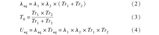
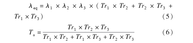
For the case of simultaneous failure of two components, the equivalent failure rate (λₑ), average outage duration (r), and annual outage time (u) are expressed as follows:
For the case of simultaneous failure at three levels, it is expressed as follows:
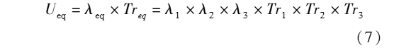
Considering all failure modes, the total failure rate and the total annual outage time can be calculated as follows:
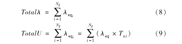
Table 3 shows the reliability analysis results for the loads.

Now, the same calculation is performed for the feeders on the other 230 kV bus. Table 4 shows the results related to load point LS.

5 Conclusion
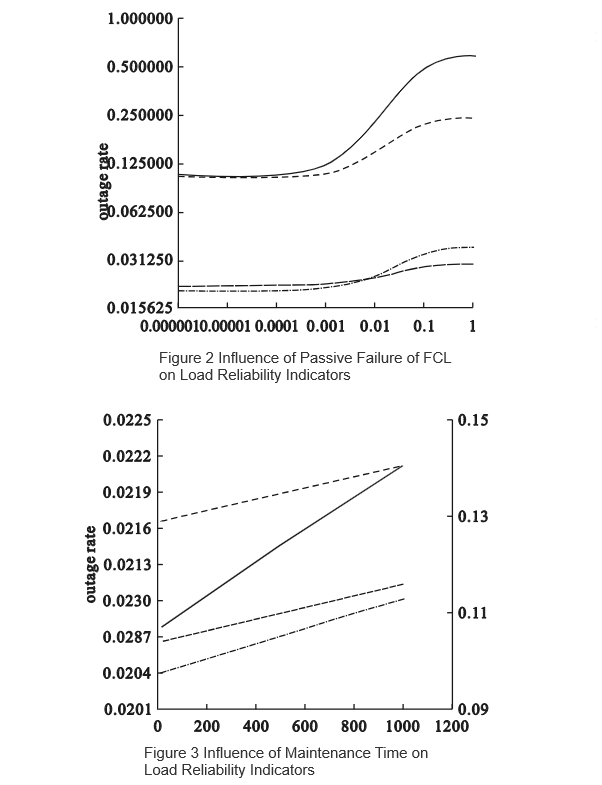
This paper presents the application of fault current limiters (FCLs) in enhancing substation reliability, describes the mathematical model and procedure for reliability calculation, and evaluates the impact of FCL implementation on substation reliability. The results indicate that substation reliability is improved by employing FCLs. A sensitivity analysis is also conducted to examine the influence of various parameters—such as the active failure rate, passive failure rate, and repair time of the FCL—on the reliability indices.


