What tests are required for dry-type transformers?

Oliver Watts
07/01/2025

1 Pre - commissioning Inspection
As a front - line tester, before formally commissioning a dry - type transformer, I need to carry out a comprehensive and systematic inspection. First, I conduct a visual inspection of the transformer body and its accessories, carefully checking for mechanical damage or deformation. Then, I check whether the leads of the high - and low - voltage windings are firmly connected and whether the bolt tightening torque meets the standard requirements (usually 40 - 60N·m). This torque value is related to the reliability of the electrical connection, and I strictly control it every time.Next, I inspect the cooling system: start the fan to check if the rotation direction is correct and if the control circuit wiring is accurate.
These details affect the cooling effect and are crucial for the stable operation of the transformer. I also measure the grounding resistance of the transformer foundation to ensure it is not greater than 4Ω; check the reliability of the grounding device and whether the cross - section of the grounding wire meets the requirements. Grounding is an important guarantee for equipment safety.In addition, I verify that the inspection certificates of all test instruments are within the validity period and calibrate them. If the instruments are inaccurate, the test data will be meaningless. At the same time, I check the consistency between the transformer nameplate parameters and the design requirements, and review the completeness of the random documents. These documents are also useful for future operation and maintenance, so they must be treated rigorously.
2 Insulation Resistance Test
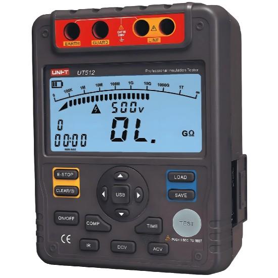
For the insulation resistance test, I use a 2500V megohmmeter to measure the insulation resistance values between high voltage to ground, low voltage to ground, and high voltage to low voltage respectively. Pay attention to the test environment: it should be carried out under the conditions of an ambient temperature of 20±5℃ and a relative humidity not greater than 85%. The environment affects the test results, so I will confirm in advance whether the environment meets the standards.
Before measurement, I discharge the tested winding and wipe all bushing surfaces clean to avoid dirt affecting the data. The measurement time lasts for 1min, and I record the readings at 15s and 60s to calculate the absorption ratio. According to the transformer capacity level, the test results must meet the standard requirements in Table 1. After each measurement, I carefully compare with the standards to judge whether it is qualified.
3 Transformation Ratio and Polarity Test
I use a digital transformation ratio tester to measure the voltage ratios of the transformer at each tap - changer position. During measurement, I strictly follow the “same - name - terminal measurement method”, that is, measure the corresponding terminals of the same phase on the high - and low - voltage sides in sequence to ensure accurate data. The error between the measured actual transformation ratio and the nameplate nominal value should not exceed ±0.5%. If it exceeds, I need to find out the problem.
For the polarity test, I use the DC voltage method: connect a 10V DC power supply and a half - deflection ammeter, and judge the polarity by observing the swing direction of the ammeter pointer. For three - phase transformers, I also need to measure the phase angle to verify the correctness of the wiring group. For the commonly used YNd11 wiring group, the phase angle should be 30°, with an error not exceeding ±1°. If these parameters are wrong, the transformer cannot be connected to the grid normally, so I must confirm them repeatedly.
4 No - load and Load Tests
During the no - load test, I apply the rated voltage on the low - voltage side to measure the no - load current I₀ and no - load loss P₀. The no - load current should not exceed 3% of the rated current, and the no - load loss should not exceed 110% of the factory value. These two data reflect the performance of the transformer core, and I will measure and record them accurately.
For the load test, I use the low - voltage high - current method to measure the load loss Pₖ and impedance voltage Uₖ%. During the test, I monitor the winding temperature. If the temperature exceeds 95℃, I immediately stop the test, as excessive temperature can damage the equipment. The test data must meet the requirements in Table 2, and I treat each item rigorously to ensure reliable test results.
5 Protection Device Commissioning
For the commissioning of protection devices, I mainly perform setting and testing for systems such as temperature protection, over - current protection, and differential protection. The temperature protection is set with two - level alarm values, usually 90℃ and 100℃; the setting value of over - current protection is 1.5 times the rated current, with an action time of 0.5s; the sensitivity coefficient of differential protection should be greater than 2, and CT polarity testing and disconnection inspection must also be carried out.
Each protection device needs to undergo an actual action test to verify the reliability of the tripping circuit. I use a secondary injection tester to simulate various fault conditions to check if the protection device can operate correctly. At the same time, I check the remote transmission function of the fault signal to ensure normal communication with the monitoring system. The protection device is the “bodyguard” of the transformer and must be commissioned in place.
6 Temperature Monitoring System Commissioning
The temperature monitoring system is crucial for the safe operation of dry - type transformers. During commissioning, I first calibrate the accuracy of the temperature sensor: use a standard temperature source for comparison and calibration, and control the error within ±1℃. Set the graded alarm values, usually four temperature points: early warning at 95℃, first - level alarm at 100℃, second - level alarm at 110℃, and tripping at 120℃.
I check the automatic start - stop function of the fan: the fan should start automatically when the temperature rises to 85℃ and stop automatically when it drops to 65℃. I will simulate temperature changes for testing. Confirm that the display function of the temperature display unit is normal and the temperature values of each measurement point are displayed accurately. Test the transmission function of the temperature alarm signal to ensure it can be accurately connected to the substation control system. Finally, establish a complete commissioning record, including the calibration data of each measurement point, alarm settings, and linkage test results. These records are also useful for future operation and maintenance tracing.
Oliver Watts

Hey! I'm Oliver Watts, an electrical engineer in Inspection and Testing. With years of hands - on experience, I ensure electrical systems meet top safety and performance standards. Using advanced gear, I conduct diverse tests, easily spotting issues in both large - scale industrial and small - scale commercial setups. I love teaming up, sharing knowledge, and keeping up with industry regs. Also, I'm skilled at data analysis with software. If you're into electrical inspection or just want to chat engineering, reach out. Let's connect and explore!

A Quick Verification Method for Low-Voltage Current Transformers
To ensure safe operation of the power system, power equipment operation must be monitored/measured. General devices can’t connect to primary high - voltage equipment directly; instead, large primary currents are scaled down for current transformation, electrical isolation, and use by measurement/protection devices. For AC large - current measurement, conversion to a unified current eases secondary instrument use.Current transformers split into measurement - and protection - type, with accu
Oliver Watts
07/16/2025
What Tests Are Required for a Qualified AIS Voltage Transformer?
Hey everyone! I’m Oliver, an experienced electrician with over a decade in the power system industry. Today, we’re diving into a practical topic — what tests are required to ensure an Air Insulated Switchgear (AIS) voltage transformer is qualified? These tests are crucial not only for ensuring the device operates correctly but also for maintaining the safety and stability of the power grid. Let’s get started!1. Visual InspectionFirst Look MattersThe very first step is a v
Oliver Watts
07/14/2025
What Tests Must a Qualified AIS Current Transformer Undergo?
Hey everyone, I’m Oliver, a 10-year veteran in the power system industry. Today we’re going to talk about a very practical topic — how do you know if a current transformer (CT) used in Air Insulated Switchgear (AIS) is truly qualified? This isn’t just about meeting technical specs; it’s directly tied to equipment safety, grid stability, and accurate metering.Let’s dive in — based on my real-world experience.IntroductionIn substations or distribution syst
Oliver Watts
07/12/2025
What are the routine tests for outdoor voltage transformers?
1. IntroductionOutdoor voltage transformers are key equipment for ensuring the safety of electrical apparatus. Scientific and comprehensive test analysis is required to avoid hazards and property losses caused by improper operation. Test analysis can guide the formulation of operation strategies and precautions, ensure the stable operation of equipment, and maximize economic and social benefits.2. Concept of Outdoor Voltage TransformersAn outdoor voltage transformer is essentially an outdoor ste
Oliver Watts
07/10/2025
Inquiry
Download
IEE-Business is dedicated to serving the personnel in the global power industry.
Join IEE-Business, not only can you discover power equipment and power knowledge, but also canhnd like - minded friends!