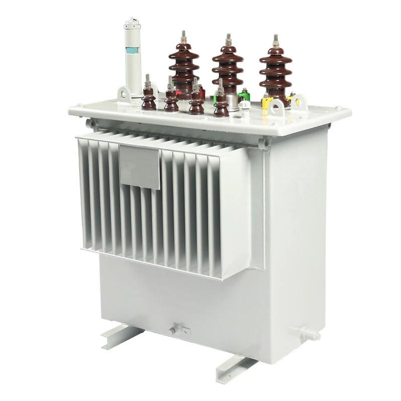
Selecting Energy Efficient Distribution Transformers

04/12/2025

Definition of Transformer Losses

Transformer losses can be mainly categorized into two types: no - load losses and load losses. These losses are ubiquitous across all types of transformers, irrespective of their application scenarios or power ratings.
However, there are two additional types of losses: extra losses induced by harmonics, and losses that are especially relevant for larger transformers – cooling or auxiliary losses, which result from the use of cooling equipment such as fans and pumps.

No - Load Losses

These losses occur in the transformer core whenever the transformer is energized (even when the secondary circuit is open - circuited). Also known as iron losses or core losses, they remain constant.
No - load losses consist of:

Hysteresis Losses

These losses are caused by the frictional motion of magnetic domains within the core laminations as they are magnetized and demagnetized by the alternating magnetic field. They depend on the type of material used for the core.
Hysteresis losses typically account for over half of the total no - load losses (approximately 50% to 70%). In the past, this proportion was smaller (owing to a higher contribution from eddy current losses, especially in relatively thick sheets that hadn't undergone laser treatment).

Eddy Current Losses

These losses are induced by varying magnetic fields that generate eddy currents in the core laminations, thereby producing heat.
These losses can be mitigated by constructing the core from thin, laminated sheets insulated from one another by a thin varnish layer to reduce eddy currents. Currently, eddy current losses generally make up 30% to 50% of the total no - load losses. When evaluating efforts to enhance the efficiency of distribution transformers, the most significant progress has been made in reducing these losses.
There are also minor stray and dielectric losses in the transformer core, typically accounting for no more than 1% of the total no - load losses.

Load Losses

These losses are commonly known as copper losses or short - circuit losses. Load losses fluctuate according to the transformer's loading conditions.
Load losses consist of:

Ohmic Heat Loss

Sometimes called copper loss, as it is the dominant resistive component of load loss. This loss occurs in the transformer windings and is due to the resistance of the conductor.
The magnitude of these losses increases in proportion to the square of the load current and is also proportional to the resistance of the winding. It can be reduced by increasing the cross - sectional area of the conductor or shortening the winding length. Using copper as the conductor helps balance weight, size, cost, and resistance; increasing the conductor diameter within the bounds of other design constraints can further reduce losses.

Conductor Eddy Current Losses

Eddy currents, resulting from the magnetic fields of alternating current, also occur in the windings. Reducing the conductor's cross - sectional area can decrease eddy currents, so stranded conductors are employed to achieve the required low resistance while controlling eddy current losses.
This can be avoided by using a continuously transposed conductor (CTC). In a CTC, the strands are frequently transposed to average out flux differences and equalize the voltage.

Professionalism builds strength. As an expert in the installation and operation of electrical equipment, I am proficient in the installation process and strictly adhere to standards. I skillfully master the operation essentials and can swiftly eliminate faults. With a heart that constantly explores new knowledge, I illuminate the path to the efficient operation of electrical equipment.

What Should Be Noted During the Installation Process of Indoor Load Switches?
The installation quality of indoor load switches directly affects their operational safety and service life. It must be carried out focusing on four core principles: "safety protection, standardized wiring, mechanical compatibility, and insulation assurance." Specific precautions are as follows:1.Basic Preparation and Safety Protection Before Installation: Verify that the switch model and specifications (e.g., rated voltage, current) match the actual power distribution requirements to avoid "usi
08/27/2025
Process Details for the Selection and Installation of 10kV Pole-Mounted Drop-Out Fuses
Fuses are connected in series in a circuit. When the current through the fuse element is less than or equal to its rated current, the element will not melt. Only when the current exceeds the rated value and reaches the fusing current will the element melt. When a short circuit (or overload) current occurs in the line, the current through the fuse element exceeds the specified value, causing the element to overheat and melt, thereby automatically interrupting the circuit. This prevents damage to
08/27/2025
Fundamentals of High-Voltage Fuses with High Breaking Capacity Used in Substations
In the power plants and substations of various voltage levels that we operate and maintain, high-voltage current-limiting fuses are widely used, primarily for protecting voltage transformers, small transformers, and small high-voltage motors. So why are they called high-breaking-capacity fuses? And why can't ordinary fuses be used? Today, let's learn about this topic together.High-breaking-capacity fuses, also known as high-voltage current-limiting fuses, differ from ordinary fuses in two main a
08/27/2025
Operational Safety Procedures and Maintenance Requirements for Low-Voltage Pole-Mounted Circuit Breakers
Safe operation and regular maintenance of low-voltage pole-mounted circuit breakers are essential for long-term system reliability.1. Operational Safety ProceduresOperations must be strictly regulated under dispatch control, following the "Three Tickets and Two Systems" (work permit, operation ticket, emergency repair order; read-back and supervision systems). Operation tickets must use dual equipment identifiers (e.g., "XX kV XX Line XXX Circuit Breaker") and list detailed steps and safety meas
08/21/2025
Inquiry
Download
IEE-Business is dedicated to serving the personnel in the global power industry.
Join IEE-Business, not only can you discover power equipment and power knowledge, but also canhnd like - minded friends!