• Product
  • Suppliers
  • Manufacturers
  • Solutions
  • Free tools
  • Knowledges
  • Experts
  • Communities
Search


What is the problem with cascading trips in electrical distribution panels?

Felix Spark
Felix Spark
Field: Failure and maintenance
China

Very often, the lowest-level circuit breaker does not trip, but the upstream (higher-level) one does! This causes a large-scale power outage! Why does this happen? Today, we’ll discuss this issue.

Main Causes of Cascading (Unintended Upstream) Tripping

  • The main circuit breaker’s load capacity is smaller than the total load capacity of all downstream branch breakers.

  • The main breaker is equipped with a residual current device (RCD), while the branch breakers are not. When appliance leakage current reaches or exceeds 30 mA, the main breaker trips.

  • Mismatched protection coordination between two levels of breakers—use breakers from the same manufacturer whenever possible.

  • Frequently operating the main breaker under load causes contact carbonization, leading to poor contact, increased resistance, higher current, overheating, and eventual tripping.

  • The downstream breaker lacks proper protection settings to correctly identify faults (e.g., single-phase ground fault without zero-sequence protection).

  • Aging breakers result in prolonged shunt-trip operation time; replace them with breakers whose actual tripping time is shorter than that of the upstream breaker.

Solutions for Cascading Tripping

If an upstream circuit breaker trips due to cascading:

  • If a branch protection relay has operated but its breaker did not trip, manually open that branch breaker first, then restore the upstream breaker.

  • If none of the branch protections have operated, inspect all equipment within the affected area for faults. If no fault is found, close the upstream breaker and re-energize each branch circuit one by one. When energizing a particular branch causes the upstream breaker to trip again, that branch breaker is faulty and should be isolated for maintenance or replacement.

For a circuit breaker to trip, two conditions must be met:

  • The fault current must reach the set threshold.

  • The fault current must persist for the set time duration.

Therefore, to prevent cascading trips, both current settings and time settings must be properly coordinated between breaker levels.

For example:

  • The first-level (upstream) breaker has an overcurrent protection setting of 700 A with a time delay of 0.6 seconds.

  • The second-level (downstream) breaker should have a lower current setting (e.g., 630 A) and a shorter time delay (e.g., 0.3 seconds).

In this case, if a fault occurs within the protection zone of the second-level breaker, even if the fault current exceeds the upstream breaker’s threshold, the downstream breaker will clear the fault at 0.3 seconds—before the upstream breaker’s 0.6-second timer completes—thus preventing it from tripping and avoiding cascading.

This leads to several key points:

  • The same principle applies to all fault types—whether short-circuit or ground faults—coordination relies on both current magnitude and time duration.

  • Time coordination is often more critical because fault currents may simultaneously exceed the pickup settings of multiple breakers.

  • Even if settings appear correctly coordinated on paper, real-world performance may still result in cascading trips. Why? Because the total fault-clearing time includes not only the protection relay’s operating time but also the mechanical opening time of the breaker itself. This mechanical time varies by manufacturer and model. Since protection times are in milliseconds, even small differences can disrupt coordination.

For instance, in the above example, the second-level breaker is supposed to clear the fault in 0.3 seconds. But if its mechanical mechanism is slow and takes 0.4 seconds to fully interrupt the current, the upstream breaker may already detect that the fault has lasted 0.6 seconds and trip as well—causing a cascading event.

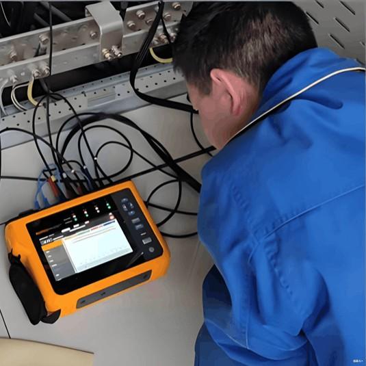
Therefore, to ensure proper coordination and prevent cascading trips, actual breaker operation times must be verified using relay protection test equipment. Coordination should be based on real measured total clearing times, not just theoretical settings.

Give a tip and encourage the author!
Recommended
What are the hazards of high-order harmonics to electrical equipment?
Voltage distortion in AC power systems causes unequal intervals between the firing pulses of the control angle in conventional converters, and through positive feedback, it amplifies the system voltage distortion, resulting in unstable rectifier operation. In inverters, continuous commutation failures may occur, preventing normal operation and even damaging commutation equipment.For star-connected transformers, third-order and triplen harmonics can cause third-harmonic oscillation when the windi
Felix Spark
11/06/2025
How to Identify Internal Faults in a Transformer?
Measure DC resistance: Use a bridge to measure the DC resistance of each high- and low-voltage winding. Check whether the resistance values among phases are balanced and consistent with the manufacturer’s original data. If phase resistance cannot be measured directly, line resistance may be measured instead. The DC resistance values can indicate whether the windings are intact, whether there are short circuits or open circuits, and whether the contact resistance of the tap changer is normal. If
Felix Spark
11/04/2025
What Are the Common Inverter Fault Symptoms and Inspection Methods? A Complete Guide
Common inverter faults mainly include overcurrent, short circuit, ground fault, overvoltage, undervoltage, phase loss, overheating, overload, CPU malfunction, and communication errors. Modern inverters are equipped with comprehensive self-diagnostic, protection, and alarm functions. When any of these faults occurs, the inverter will immediately trigger an alarm or shut down automatically for protection, displaying a fault code or fault type. In most cases, the fault cause can be quickly identifi
Felix Spark
11/04/2025
What Are the Top 10 Taboos and Precautions in the Installation of Distribution Boards and Cabinets?
There are many taboos and problematic practices in the installation of distribution boards and cabinets that must be noted. Especially in certain areas, improper operations during installation may lead to serious consequences. For cases where the precautions were not followed, some corrective measures are also provided here to remedy previous mistakes. Let’s follow along and take a look at common installation taboos from manufacturers regarding distribution boxes and cabinets!1. Taboo: Lighting
James
11/04/2025
Related Products
Send inquiry
Download
Get the IEE Business Application
Use the IEE-Business app to find equipment, obtain solutions, connect with experts, and participate in industry collaboration anytime, anywhere—fully supporting the development of your power projects and business.