• Product
  • Suppliers
  • Manufacturers
  • Solutions
  • Free tools
  • Knowledges
  • Experts
  • Communities
Search


How does the skin effect in conductors impact the design of high-frequency power transmission systems?

Encyclopedia
Encyclopedia
Field: Encyclopedia
0
China

The skin effect refers to the phenomenon where, under the influence of an alternating electric field, current tends to concentrate near the surface of a conductor. As frequency increases, this effect becomes more pronounced. In high-frequency power transmission systems, the skin effect can significantly impact the design. Here are the specific influences and corresponding design considerations:

Conductor Size and Shape

  • Conductor Diameter: The skin effect causes the current to primarily concentrate on the outer surface of the conductor. Consequently, the effective cross-sectional area of the conductor decreases at high frequencies, increasing resistance. To mitigate this effect, thin-walled hollow conductors (such as tubular conductors) or flat ribbon conductors can be used to increase the surface area while reducing unnecessary material.

  • Multi-Core Structure: In some cases, multiple fine conductors (such as stranded wire) can be used instead of a single thick conductor. This approach increases the total surface area, thereby reducing the impact of the skin effect at high frequencies.

Material Selection

  • High-Conductivity Materials: In high-frequency applications, choosing materials with high electrical conductivity (such as silver or copper) can reduce the skin depth, thereby decreasing resistance and losses.

  • Composite Materials: Sometimes, conductors with surfaces coated in highly conductive materials are used to improve performance at high frequencies.

Cooling Requirements

Temperature Control: The skin effect can lead to reduced current density in the center of the conductor, making it difficult for heat to dissipate from the center. Therefore, in high-frequency power transmission systems, effective cooling solutions are necessary to maintain safe operating temperatures for the conductors.

Electromagnetic Interference (EMI) and Shielding

  • Shielding Layers: High-frequency signals are prone to electromagnetic interference. To minimize interference, shielding layers are typically included in the system design to protect against external electromagnetic fields and reduce emissions from the transmission line.

  • Grounding Design:  Proper grounding design is crucial for reducing electromagnetic interference. Correct grounding can effectively suppress noise and enhance system stability.

Transmission Line Characteristics

  • Characteristic Impedance: In the design of high-frequency transmission lines, the characteristic impedance of the line needs to be considered. The skin effect can affect the impedance characteristics of the transmission line, so particular attention should be paid to matching issues to avoid reflections and signal loss.

  • Attenuation and Delay: High-frequency signals may experience attenuation and delay during transmission, especially over long distances. The skin effect can contribute to additional attenuation, so the relationship between signal integrity and transmission distance must be considered during design.

Connector and Termination Design

Connection Design: In high-frequency systems, the design of connectors and terminations significantly impacts performance. The skin effect requires that connection points have good contact and low-impedance paths to minimize signal loss.

Conclusion

The skin effect presents unique challenges in the design of high-frequency power transmission systems. By appropriately selecting conductor materials, optimizing conductor geometry, employing suitable cooling methods, enhancing electromagnetic compatibility design, and accurately matching the characteristic impedance of transmission lines, the impacts of the skin effect can be effectively managed, ensuring efficient operation and reliability of the system.

Give a tip and encourage the author!
Recommended
Composition and Working Principle of Photovoltaic Power Generation Systems
Composition and Working Principle of Photovoltaic (PV) Power Generation SystemsA photovoltaic (PV) power generation system is primarily composed of PV modules, a controller, an inverter, batteries, and other accessories (batteries are not required for grid-connected systems). Based on whether it relies on the public power grid, PV systems are divided into off-grid and grid-connected types. Off-grid systems operate independently without relying on the utility grid. They are equipped with energy-s
Encyclopedia
10/09/2025
How to Maintain a PV Plant? State Grid Answers 8 Common O&M Questions(2)
1. On a scorching sunny day, do damaged vulnerable components need to be replaced immediately?Immediate replacement is not recommended. If replacement is necessary, it is advisable to do so in the early morning or late afternoon. You should contact the power station’s operation and maintenance (O&M) personnel promptly, and have professional staff go to the site for replacement.2. To prevent photovoltaic (PV) modules from being hit by heavy objects, can wire mesh protective screens be install
Encyclopedia
09/06/2025
How to Maintain a PV Plant? State Grid Answers 8 Common O&M Questions(1)
1. What are the common faults of distributed photovoltaic (PV) power generation systems? What typical problems may occur in various components of the system?Common faults include inverters failing to operate or start due to voltage not reaching the startup set value, and low power generation caused by issues with PV modules or inverters. Typical problems that may occur in system components are burnout of junction boxes and local burnout of PV modules.2. How to handle common faults of distributed
Leon
09/06/2025
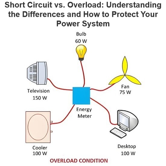
Short Circuit vs. Overload: Understanding the Differences and How to Protect Your Power System
One of the main differences between a short circuit and an overload is that a short circuit occurs due to a fault between conductors (line-to-line) or between a conductor and earth (line-to-ground), whereas an overload refers to a situation where equipment draws more current than its rated capacity from the power supply.Other key differences between the two are explained in the comparison chart below.The term "overload" typically refers to a condition in a circuit or connected device. A circuit
Edwiin
08/28/2025
Send inquiry
Download
Get the IEE Business Application
Use the IEE-Business app to find equipment, obtain solutions, connect with experts, and participate in industry collaboration anytime, anywhere—fully supporting the development of your power projects and business.