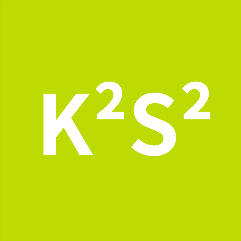
E = K² * S²
| k | Copper | Aluminum |
| PVC | 115 | 74 |
| G2 | 135 | 87 |
| EPR/XLPE | 143 | 87 |
| Naked | 200 |
| k | Copper | Aluminum |
| PVC | 115 | 76 |
| G2 | 135 | 89 |
| EPR/XLPE | 143 | 94 |
| Naked | 228 |
| k | Copper | Aluminum |
| PVC | 143 | 95 |
| G2 | 166 | 110 |
| EPR/XLPE | 176 | 116 |
| Naked | 228 |
Definitions
E = Admissible let - through energy ( )
k = Constant that depends on the conductor and on the type of cable insulation
S = Wire size ( )
A = Current ( A )
s = Time ( sec )
This tool calculates the maximum admissible let-through energy (I²t) that a cable can withstand under short-circuit conditions, based on IEC 60364-4-43 and IEC 60364-5-54 standards. It ensures that protective devices (e.g., circuit breakers or fuses) interrupt fault currents before the conductor overheats and damages insulation.
1. Conductor Type: Phase conductor, single-core protective conductor (PE), or multi-core cable's protective conductor (PE)
2. Wire Size (mm²): Cross-sectional area of the conductor, affecting thermal capacity
3. Conductor Material: Copper (Cu) or Aluminum (Al), influencing resistivity and heat generation
4. Insulation Type:
Thermoplastic (PVC)
Thermosetting (XLPE or EPR)
Mineral thermoplastic (PVC) covered
Mineral bare sheath or bare conductor (not exposed to touch, restricted area)
Mineral bare sheath or bare conductor (exposed to touch, normal conditions)
Mineral bare sheath or bare conductor (fire risk environment)
Mineral with metallic sheath used as protective conductor
1. Admissible let-through energy (kA²s) — maximum tolerable I²t value
2. Reference standard clauses: IEC 60364-4-43 and IEC 60364-5-54
3. Compliance check: whether the calculated I²t is less than the protection device’s I²t characteristic
Designed for electrical designers and installers to verify short-circuit thermal stability of cables and ensure safe operation during faults.








 Login
Login