Monitoring Technology for Open/Close Position of High-Voltage Disconnectors

In the context of high-speed operation of power systems, the opening and closing mechanism of high-voltage disconnectors in substations faces challenges such as complex operational procedures, large workloads, and low operational efficiency. With the advancement of image recognition technologies and sensor innovations, modern intelligent substations now demand higher technical standards for monitoring the open/close positions of high-voltage disconnectors during infrastructure development.
The integration of power Internet of Things (IoT) sensing technologies and wireless communication into power equipment has significantly enhanced the automation and intelligence levels of high-voltage disconnector systems—aligning with future requirements for smart grid and substation development. Therefore, it is essential to further investigate the key application aspects of position monitoring technologies for high-voltage disconnector operations based on their internal structure and technical characteristics.
1. Internal Structure of High-Voltage Disconnectors
1.1 Conductive Components
During opening/closing operations, the static contact terminal of a high-voltage disconnector is primarily constructed from copper plates. Two such copper plates are interconnected to form a contact blade, which rotates around a central axis to enable status monitoring. When closed, this assembly securely clamps onto the static contact head. A compression spring is installed between the two copper plates to regulate contact pressure between the moving and static contacts.
During operation, when currents flow in the same direction through both plates, electromagnetic attraction is generated between them, increasing contact pressure and enhancing operational stability. Additionally, galvanized steel sheets mounted on both sides of the contact blade produce noticeable magnetization under short-circuit current conditions, generating mutual attractive forces that further reinforce contact pressure and fundamentally improve the mechanical stability of the disconnector’s open/close mechanism.
1.2 Insulating Components
In the position monitoring system, the moving and static contacts are mounted on separate magnetic supports—the moving contact is fixed onto a porcelain insulator bushing. To ensure mechanical stability and electrical isolation between the moving contact and metallic structures, a porcelain pull-rod insulator is employed.
1.3 Base Structure
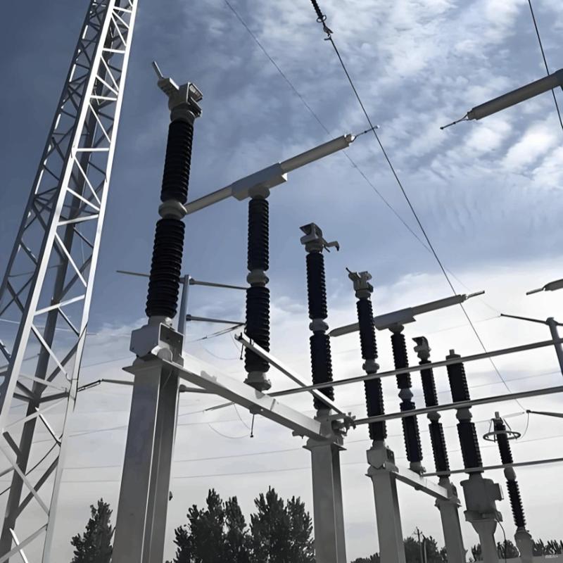
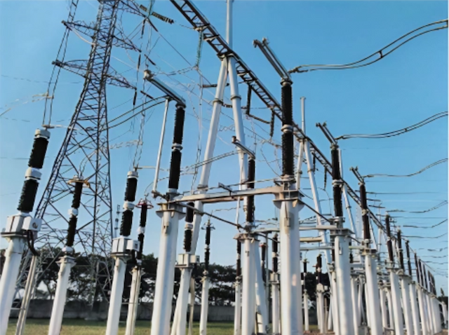
The base, typically constructed from a steel frame, serves as the mounting platform for porcelain insulators (or bushings) and the main drive shaft. It must be properly grounded. Since high-voltage disconnectors lack arc-quenching capability, they feature a clearly visible break point when open, making their open/close status visually intuitive.
2. Characteristics of Open/Close Position Monitoring Technologies
2.1 Image Recognition Technology
Image recognition offers inherent advantages in visual intuitiveness and ease of implementation. However, due to the large volume and variability of environmental image data in substation operations, advanced intelligent recognition algorithms—particularly those involving depth information processing—are required. Substation systems must accurately identify graphical data from various devices and extract distinctive features to serve as the basis for determining disconnector position status.
2.2 Modern Sensing Technologies
Modern monitoring approaches leverage attitude sensors, optical sensors, and other advanced sensing devices to track dynamic changes in disconnector position during operation. When combined with traditional contact-based detection methods, they form a “dual-confirmation” criterion for position judgment—a critical enabler of the “one-click sequential control” functionality in intelligent substations.
3. Key Application Considerations for Disconnector Position Monitoring Technologies
As substations evolve toward greater intelligence, new-generation position monitoring technologies for high-voltage disconnectors have become pivotal to smart grid infrastructure—especially to meet the demands of one-click sequential control. Engineers must select appropriate monitoring techniques based on specific system configurations to ensure reliable performance.
3.1 Image Recognition Technology
Image recognition integrates computer vision with fuzzy information processing to extract distinctive features from visual data, satisfying diverse user requirements across varying scenarios. In practice, the position of a disconnector is determined by capturing images of its open/close state and applying intelligent parameter calculation and image processing algorithms to verify compliance with operational standards.
However, this method suffers from relatively low recognition accuracy and high susceptibility to environmental interference (e.g., lighting, dust, weather), leading to increased implementation costs. To address this, real-time position data must be transmitted to centralized monitoring platforms. Current applications often incorporate intelligent substation inspection robots that use advanced computational models to achieve precise position identification.
Moreover, to fulfill China’s power grid requirements for remote-controlled disconnector verification, image monitoring systems must be tightly integrated with switch position signals. This enables accurate status determination through a four-stage process: image acquisition, feature extraction, grayscale processing, and state recognition—culminating in data upload to the control center.
During operation, ensemble computing methods can optimize local operational data, though slow system convergence remains a challenge. Thus, mechanical vision-based switch state recognition should be adopted alongside dual-threshold logic and spatial-domain filtering to suppress noise and enhance feature extraction—thereby improving recognition efficiency. Nevertheless, video surveillance systems require comprehensive, multi-angle coverage; otherwise, external electromagnetic interference may severely compromise monitoring reliability.
3.2 Optical Sensing Technology
Optical sensing involves installing laser sensors on the moving contact assembly. A laser emitter directs a beam toward a reflector; when the disconnector is in a specific position, the reflected signal is received by the sensor. If the received optical signal exceeds a predefined threshold, the electrical output signal decreases accordingly—enabling position inference based on signal variation.
To ensure operational quality, infrared laser detectors can also monitor temperature differentials across contacts, supporting the development of intelligent monitoring systems. Engineers deploy integrated setups comprising laser emitters, reflectors, and receivers to wirelessly sense the position of the moving contact head via light-beam interruption.
Real-time disconnector status must be transmitted to backend control systems via communication modules. However, this technology demands extremely precise alignment of laser emitters, reflectors, and sensors—posing significant challenges during field installation. Additionally, effective transmission distance is inherently limited. Therefore, engineers should refine existing laser-sensing architectures to develop specialized systems tailored for horizontally rotating disconnectors.
By analyzing variations in the received laser signal, technicians can reliably distinguish between open and closed states. Disconnector position states are summarized in Table 1.
| Left Contact Arm Monitoring Closed Position | Left Contact Arm Monitoring Opened Position | Right Contact Arm Monitoring Closed Position | Right Contact Arm Monitoring Opened Position | Isolator Switch Status |
| 1 | 0 | 1 |
0 | Closed Position |
| 0 | 1 |
0 | 1 | Opened Position |
| 1/0 | 1/0 | Abnormal | ||
| 1/0 | 0/1 | Abnormal |
As shown in Table 1, optical sensing technology offers a monitoring approach in practical applications that is immune to electromagnetic interference, making it suitable for a wide range of environments and scenarios. However, it exhibits notable drawbacks: relatively low stability and safety during system detection, inability to fully verify the quality of contact when the disconnector is in the closed position, and high susceptibility to adverse weather conditions such as rain, snow, humidity, and poor visibility—resulting in reduced reliability and accuracy.
3.3 Contact Point Detection Technology
Contact point detection technology determines the position of the disconnector valve based on the operating principle of auxiliary contacts. It requires installing auxiliary contact points at specific open/close positions of the disconnector, with the actual switch status inferred from the engagement of these contacts.
During operation, auxiliary contacts can be installed in either high-voltage or low-voltage zones. When placed in the high-voltage area, the mechanical motion generated by the disconnector’s opening/closing action physically actuates the auxiliary contacts. The operational state of these auxiliary contacts then directly controls or indicates the disconnector’s open or closed position, enabling highly accurate reflection of its real-time status. However, after prolonged operation, mechanical wear and misalignment may degrade performance, necessitating optimization and upgrades.
When installed in the low-voltage zone, the system relies on internal moving components within the control cabinet to mechanically trigger the auxiliary contacts, thereby completing the basic open/close operation. This method involves multi-stage transmission mechanisms to reflect the status of the contact head. If any component in this mechanical chain fails or malfunctions, the system may fail to accurately represent the true operational state of the disconnector.
4. Future Development Trends
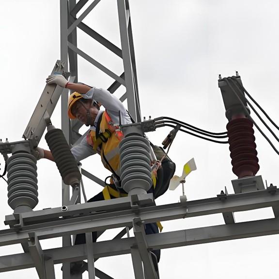
Currently, research and technological advancements in monitoring systems for high-voltage disconnector operations in China are becoming increasingly comprehensive. Nevertheless, many domestic substations still rely on traditional manual switching procedures. This approach requires operators to repeatedly execute each step on-site, resulting in inefficiencies. Even for simple signal anomalies, technicians must physically travel to the location. Long-term dependence on manual operations increases the risks of human error, missed operations, and slow switching speeds.
With the ongoing integration and advancement of technologies—including image recognition, sensor networks, laser measurement, and pressure sensing—a diverse array of methods for determining disconnector position has emerged. This technological convergence provides new research directions and foundational support for the automation and intelligence of smart high-voltage disconnectors.
5. Conclusion
In summary, monitoring the open/close position of high-voltage disconnectors involves complex and varied operational procedures. Routine maintenance still partially depends on on-site manual inspection to assess real-time operational conditions, and all operations must strictly adhere to established technical protocols. The future direction lies in integrating artificial intelligence into monitoring systems to ultimately achieve intelligent, autonomous, and reliable position detection—paving the way for next-generation smart substation infrastructure.