A Brief Discussion on the Retrofit and Application of Stationary Contacts in 220 kV Outdoor High-Voltage Disconnectors

The disconnector is the most widely used type of high-voltage switching equipment. In power systems, high-voltage disconnectors are high-voltage electrical devices used in coordination with high-voltage circuit breakers to perform switching operations. They play a critical role during normal power system operation, switching operations, and substation maintenance. Due to their frequent operation and high reliability requirements, disconnectors significantly impact the design, construction, and safe operation of substations and power plants.
The operating principle and structure of disconnectors are relatively simple. Their main characteristic is the lack of arc-quenching capability; they can only open or close circuits under no-load current or very low current conditions (typically < 2 A). High-voltage disconnectors can be classified by installation environment into outdoor and indoor types. Based on the structure of their insulating support columns, they can be further categorized as single-column, double-column, or triple-column disconnectors.
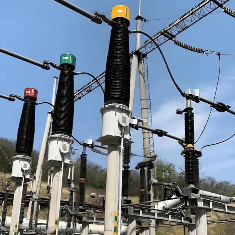
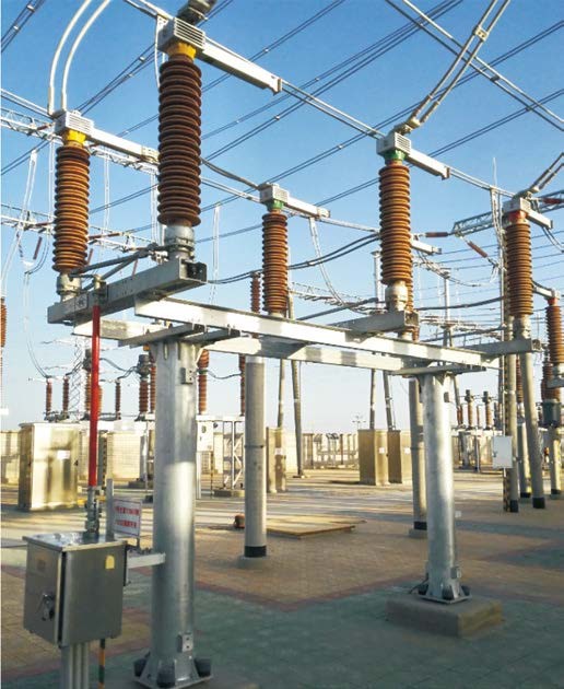
The 220 kV substation at a power plant of an aluminum enterprise is a fully automated step-down substation that has been in operation for nearly 19 years. It primarily supplies DC power to 200 kA electrolytic cells and provides production, auxiliary, and residential power to other secondary plants within the company. The outdoor 220 kV switchyard uses GW7-220 type outdoor AC high-voltage disconnectors—three-column, horizontally opening, three-phase, 50 Hz outdoor high-voltage electrical equipment.
Since commissioning in 1998, these outdoor AC high-voltage disconnectors have enabled bus transfer under no-load conditions and provided electrical isolation between de-energized equipment (such as busbars and circuit breakers under maintenance) and live high-voltage lines. After 19 years of service, widespread overheating of the disconnector contacts has been observed (infrared thermometer readings reaching up to 150°C), posing a serious safety hazard. This issue could lead to burnout of the 220 kV disconnectors, resulting in phase loss, contact welding, or arc-flash short circuits—potentially causing a complete blackout and paralysis of the entire substation system.
In response, data collection and root cause analysis were conducted, leading to the identification of the primary causes of contact overheating. Effective retrofit measures were implemented and subsequently promoted for broader application.
Structure and Operating Principle of the GW7-220 Outdoor AC High-Voltage Disconnector
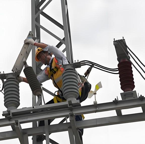
This disconnector features a three-column, horizontally rotating structure, consisting of a base, insulating support columns, a conductive system, an earthing switch (except for non-grounded versions), and a drive mechanism. The base is welded from channel steel and steel plates, with three mounting brackets: two fixed at the ends and one rotatable in the middle. Inside the channel steel housing are transmission linkages and interlocking plates. Mounting plates are welded beneath the base for secure foundation attachment. Bases are available in three configurations: non-grounded, single-grounded, and double-grounded. For grounded versions, earthing switch brackets are welded to one or both ends of the base, with earthing switches mounted accordingly, selected based on circuit requirements.
The conductive assembly is fixed atop the insulating columns and comprises a moving blade (conductive gate knife) and stationary contacts. The gate knife consists of two copper tubes connected via two copper blocks to an aluminum cover, with a cylindrical contact tip welded at the end. The stationary contacts feature a finger-type, multi-point contact design. Each contact finger has an independent tension spring, providing sufficient insertion travel to maintain reliable contact even under busbar tension forces. A return spring tilts the stationary contact slightly to ensure smooth and coordinated opening/closing actions.
The operating mechanism includes both electric and manual options. The electric mechanism uses an asynchronous motor driving a mechanical reduction gear to rotate the main shaft by 180°. Force is transmitted via connecting steel tubes to the disconnector, and linkages rotate the central insulating column by 71°, causing the moving contacts at both ends of the conductive rod to insert into or withdraw from the stationary contacts, completing closing or opening operations. Mechanical dead-center positions in the linkage provide self-locking at the end points of travel. Manual operation is available for commissioning or in case of electric mechanism failure.
Analysis of Contact Overheating Causes in Outdoor High-Voltage Disconnectors
The aluminum enterprise’s 220 kV outdoor switchyard has 24 sets of GW7-220 disconnectors serving two 220 kV incoming lines, rectifier units #1–#4, and power transformers #1 and #2, totaling 144 stationary contacts. During routine inspections, overheating was assessed by observing heat shimmer, discoloration, or temperature measurements exceeding 70°C at contact points. Statistics show that from January to December 2014, there were 13 unplanned outages due to disconnector contact overheating—averaging 1.08 incidents per month.
Repeated testing and analysis of contact dynamics revealed the following root causes:
Each stationary contact consists of six independent finger contacts with point-contact geometry, resulting in insufficient total contact area and uneven current distribution across fingers—a structural flaw.
Multiple movable contact components allow current to flow through contact springs, causing annealing, loss of elasticity, reduced contact pressure, and worsening contact resistance, which exacerbates heating.
Harsh outdoor conditions (sunlight, rain) combined with suboptimal material selection (standard steel for tension springs and contact pins) led to severe corrosion, aging, spring fatigue, degraded mechanical properties, insufficient contact force, and excessive loop resistance.
Arc erosion has caused pitting and severe oxidation on contact surfaces, further increasing resistance.
Retrofit and Preventive Measures for Stationary Contacts
Interconnect the originally independent finger contacts using flexible copper straps to increase effective contact area between moving and stationary contacts.
Replace and upgrade tension springs and pins to enhance spring force and improve contact tightness.
Apply silver plating to both moving and stationary contact surfaces.
Apply solid lubricant to contact surfaces to reduce friction and prevent oxidation.
Implement infrared temperature monitoring, especially at contact connection points, and establish a temperature database.
Conduct regular maintenance, inspection, and cleaning of disconnectors.
Verification and Application Results
Post-retrofit monitoring shows:
Under identical ambient temperature (17°C) and operating conditions, contact temperatures dropped from ~23°C (unmodified) to ~19°C (retrofitted).
Visual inspections during maintenance revealed significantly fewer arc-damage spots on retrofitted contacts compared to unmodified ones.
As of this writing, 5 disconnector units (30 stationary contacts) have been retrofitted. This technical solution is being progressively rolled out across all GW7-220 disconnectors in the company’s 220 kV outdoor switchyard.
Conclusion
Through systematic analysis of widespread contact overheating in GW7-220 outdoor AC high-voltage disconnectors, targeted modifications to stationary contacts were successfully developed and implemented. This initiative has significantly enhanced power supply safety and operational stability, while also providing valuable experience for future operation, maintenance, and servicing of GW7-220 disconnectors.