Introduction
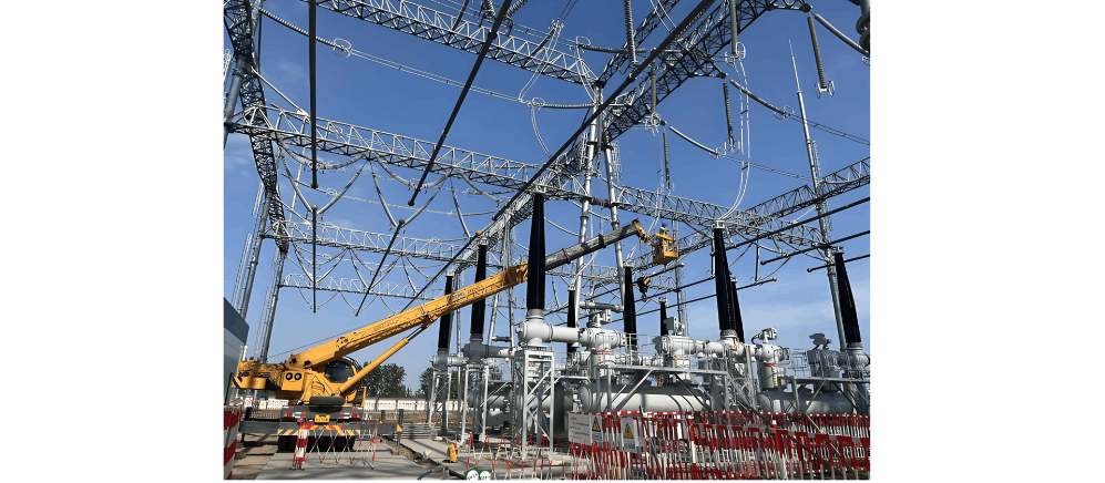
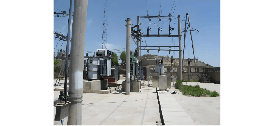
Within the intricate network of power distribution for industrial complexes, transformer substations stand as pivotal hubs. These facilities play a critical role in ensuring a stable, efficient, and safe electricity supply to power the diverse machinery and processes within industrial sites. In this blog post, we'll explore the realm of transformer substations, examining their design, functions, safety protocols, and their integral role in energizing industrial complexes.
The Foundation of Power Distribution
What is a Transformer Substation?
A transformer substation serves as a key component in the power distribution network of an industrial complex. Its primary function is to convert and distribute electrical energy from the high-voltage transmission grid to the lower voltage levels required for various industrial processes. This transformation is essential for minimizing energy losses and ensuring compatibility with on-site machinery and equipment.
Components of a Transformer Substation
Power Transformers
At the core of every substation lie power transformers. These devices facilitate the conversion of high-voltage electricity from the grid to the lower voltages needed for industrial operations. The selection of transformer type—such as oil-filled or dry-type—depends on factors including power demand, environmental constraints, and safety requirements.
Switchgear and Circuit Breakers
Switchgear and circuit breakers are integral components responsible for controlling and protecting the substation's electrical circuits. They play a vital role in isolating faulty sections, safeguarding equipment, and enabling maintenance without disrupting the entire system.
 Protection and Control Systems
Modern transformer substations are outfitted with sophisticated protection and control systems. These systems monitor parameters such as voltage, current, and temperature, enabling rapid fault response and ensuring the substation operates safely and reliably.
Safety Considerations in Transformer Substations
Fire Prevention and Suppression
Given the potential fire risks associated with electrical equipment, transformer substations incorporate robust fire prevention measures. Oil-filled transformers may use fire-resistant oils, while suppression systems—such as sprinklers or inert gas systems—are deployed to quickly extinguish flames if they occur.
Environmental Considerations
Transformer substations must comply with environmental standards, particularly regarding oil containment and spill control. Secondary containment systems and spill barriers help mitigate environmental impact in the event of oil leaks or spills.
 Design and Installation
Layout and Spacing
Efficient design and strategic equipment spacing are critical for safety and optimal performance. The layout must account for factors like maintenance accessibility, ventilation, and the minimization of electromagnetic interference.
Scalability and Future Expansion
Anticipating the future growth of industrial complexes is essential in substation design. Scalability considerations ensure the substation can accommodate additional transformers or equipment as the facility expands.
Conclusion
In summary, transformer substations form the backbone of power distribution systems in industrial complexes. Their design, components, and safety features are carefully integrated to ensure a reliable, safe, and efficient electricity supply for the machinery driving industrial processes. As industries evolve, transformer substations will adapt too—with innovations in smart grid technologies and sustainable practices shaping the future of industrial power distribution. Understanding these substations' complexities is key to unlocking the full potential of a safe, efficient, and resilient industrial power infrastructure.


