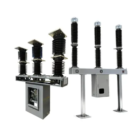
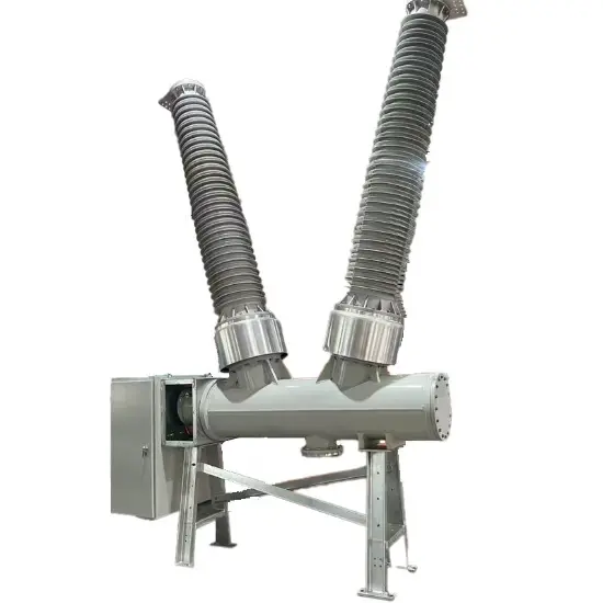
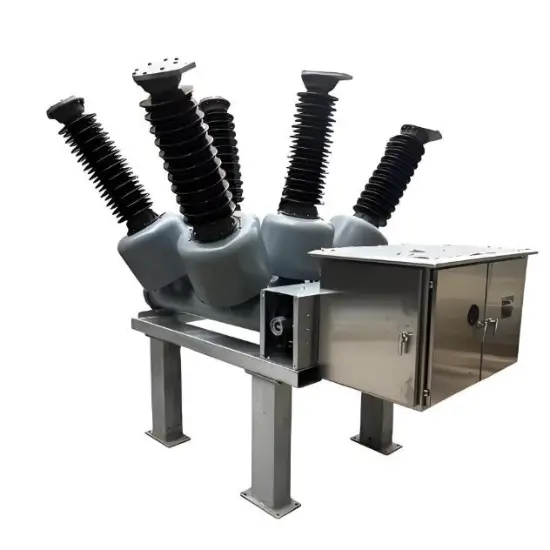
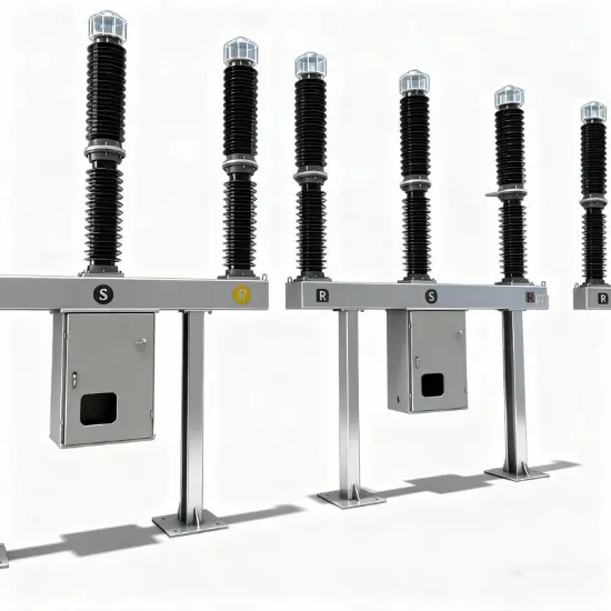
The floor - mounted tank - type circuit breaker is a crucial control and protection device in substations and power systems. It is mainly used to interrupt, close, and carry normal load currents in lines, and to cut off short - circuit currents during system failures. Composed of components such as interrupting elements, insulating bushings, bushing - type current transformers, arc - extinguishing chambers, operating mechanisms, and grounding casings, the arc - extinguishing chamber of the floor - mounted tank - type circuit breaker is housed within a grounded metal casing .
SF₆ serves as both the insulating and arc - extinguishing medium for tank - type circuit breakers. In a uniform electric field, its insulation strength is approximately three times that of air, and its arc - extinguishing capacity is around 100 times that of air. As a result, SF₆ circuit breakers are characterized by a compact structure and a small footprint. Additionally, floor - mounted tank - type circuit breakers offer advantages such as a low equipment center of gravity, stable structure, good seismic performance, built - in current transformers, strong resistance to dirt, and convenient maintenance.
However, during the manufacturing, assembly, transportation, and operation of tank - type circuit breakers, insulation defects may occur due to factors such as poor processing, collisions, impacts, and switching operations. Typical insulation defects include protruding metal objects on conductors or casings, floating electrodes, and free metal particles. When the electric field strength concentrated at the insulation defect reaches the breakdown field strength of the area under the test voltage or rated voltage, partial discharge (PD) occurs. Partial discharge is the main cause of insulation degradation in circuit breakers and a precursor to insulation failures. Therefore, online monitoring of partial discharge signals can detect insulation defects before a failure occurs, which is a vital means to ensure the safe and stable operation of floor - mounted tank - type circuit breakers and the power system.
Based on the physical signals generated during discharge, the main partial discharge detection methods for circuit breakers are the pulsed current method, the ultrasonic method (AE), the transient earth voltage method (TEV), and the ultra - high frequency method (UHF) [2 - 3]. This article combines experimental and on - site experience to review various partial discharge detection and analysis techniques for SF₆ floor - mounted tank - type circuit breakers and summarize the characteristics of each method.
Pulsed Current Method
When partial discharge occurs, the movement of charges generates a pulsed current, which can be detected by a coupling device or current sensor connected in the test circuit. The pulsed current method is the only method specified in IEC 60270 and relevant standards for quantitative measurement of partial discharge. Other methods are mainly used for the detection or location of partial discharge. The pulsed current method boasts high sensitivity, yet it is highly susceptible to on - site electromagnetic interference. Thus, it is necessary to extract the faint discharge signals from the detected signals. The physical quantity representing the magnitude of partial discharge is the apparent charge q, which can be obtained by the following formula.

In the formula, i(t ) represents the pulsed current of partial discharge, Um(t) is the pulsed voltage, Rm is the detection impedance value, and q is the apparent charge, with the unit of pC (picocoulomb).

The pulsed current method based on current sensors is suitable for online partial discharge detection. High - frequency current sensors typically operate within a frequency range of 16 kHz to 30 MHz and are designed in a clamp - on structure, facilitating their installation at the grounding end of floor - mounted tank - type circuit breakers.
Ultrasonic Method
Partial discharge causes intense molecular collisions, generating ultrasonic waves that propagate within the circuit breaker. Ultrasonic sensors installed on the circuit breaker casing can detect partial discharge signals. The piezoelectric elements inside ultrasonic sensors convert the ultrasonic signals generated by partial discharge into voltage signals, which are then transmitted to the detection circuit. The detection circuit for the ultrasonic method mainly consists of a decoupler (used to separate power supply signals from ultrasonic signals), a signal amplifier, and a filter.
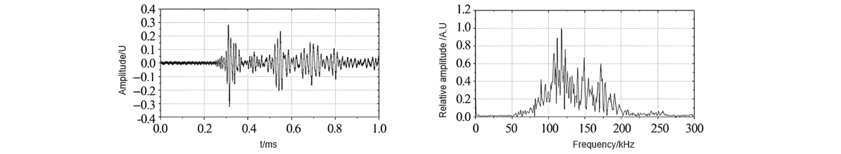
The time - domain and frequency - domain signals of ultrasonic waves from partial discharge within floor - mounted tank - type circuit breakers are shown in Figure 2, with the frequency range mainly distributed between 50 and 250 kHz. The ultrasonic method offers advantages such as low cost, easy installation, strong resistance to electromagnetic interference, and suitability for partial discharge location. However, the internal insulation structure of circuit breakers is complex, and ultrasonic waves travel slowly and experience significant attenuation in SF₆ gas, necessitating the identification of an optimal detection position.
Ultra - High Frequency (UHF) Method
The rise time and duration of the current pulses generated by partial discharge are on the nanosecond scale, exciting electromagnetic waves with equivalent frequencies in the ultra - high frequency range of 300 MHz to 3 GHz. Currently, the detection frequency range of most UHF sensors on the market is 300 MHz to 1.5 GHz. Due to the weak and high - frequency nature of the signals, the UHF method requires conditioning the input signals through filtering circuits, amplifying circuits, and integrating circuits before transmitting them to a data acquisition card for subsequent analysis.
Meanwhile, when using the UHF method, it is necessary to eliminate noises such as communication signals and lighting power supply signals from both software and hardware aspects. The UHF method features high sensitivity, strong anti - interference ability, and is suitable for partial discharge location. The phase - resolved partial discharge (PRPD) pattern of UHF signals from partial discharge at floating potential is shown in Figure 3, which contains information about the discharge amplitude, phase, and number of occurrences.

Transient Earth Voltage (TEV) Method
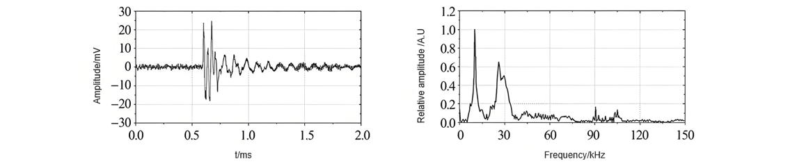
When the electromagnetic waves generated by partial discharge propagate to the metal enclosure of a floor - mounted tank - type circuit breaker, an induced current is generated on the surface of the enclosure, resulting in a transient earth voltage across the wave impedance of the grounding body. The working principle of a TEV sensor can be equivalent to that of a capacitive voltage divider. It determines the occurrence of partial discharge by detecting the voltage across the equivalent capacitor between the sensor electrode and the insulating layer. The transient earth voltage signals of partial discharge inside an SF₆ circuit breaker are shown in Figure 4, with the main frequency range being 1 - 100 MHz. The TEV method is characterized by its ease of use and the absence of a need for an additional detection circuit.
Partial Discharge Analysis Methods
Partial discharge analysis methods are employed to assess the risk level of discharges, denoise signals, and extract discharge characteristics for fault type classification. These methods mainly include the pulse waveform method, phase - resolved partial discharge (PRPD) pattern method, three - phase amplitude relationship pattern method, time - frequency pattern method, and time - based statistical characteristic method.
The pulse waveform method analyzes a single discharge waveform based on parameters such as rise time, fall time, pulse width, kurtosis, and skewness. The PRPD pattern method accumulates partial discharge signals under AC power - frequency voltage to obtain the phase, amplitude, and occurrence number distribution characteristics of the discharges. Hence, it is also known as the \(\varphi -q -n\) pattern method. The three - phase amplitude relationship pattern method is used for analyzing partial discharges under three - phase AC voltage.
It acquires the discharge distribution characteristics by collecting the discharge amplitudes of a unified discharge signal under different phase voltages. The time - frequency pattern method collects discharge pulses, calculates their equivalent time and equivalent frequency, and plots the discharge distribution pattern in the equivalent time - equivalent frequency domain. The time - based statistical characteristic method is applicable to the analysis of partial discharges under high - voltage direct current. It statistically analyzes the discharge distribution characteristics based on the magnitude of the discharge quantity and the time difference between discharge pulses.
For the location of partial discharges inside SF₆ floor - mounted tank - type circuit breakers, the absolute time - difference method or the relative time - difference method can be adopted. The absolute time - difference method uses the discharge current pulse signal or the ultra - high frequency (UHF) signal as the starting time of the discharge. After calculating the time difference between the ultrasonic signal and the discharge starting signal, it locates the discharge source. The relative time - difference method only uses multiple ultrasonic sensors installed at different positions on the circuit breaker tank. It determines the location of insulation defects by calculating the time difference between each ultrasonic signal and the reference ultrasonic signal.
Conclusion
Online monitoring of partial discharges can effectively assess the insulation performance of SF₆ floor - mounted tank - type circuit breakers before a fault occurs, and it is one of the important means to ensure their safe and stable operation. This article reviews the detection and analysis methods of partial discharges in floor - mounted tank - type circuit breakers, combining experimental and on - site experience.
During on - site applications, multiple detection means and analysis methods should be used to improve the accuracy and reliability of online monitoring. Meanwhile, in line with the requirements of the construction of the ubiquitous power Internet of Things, implementing key technologies such as wireless passive sensing, low - power - consumption wireless communication networks, edge computing, and big data represents the future development trend of partial discharge detection for floor - mounted tank - type circuit breakers.