• Product
  • Suppliers
  • Manufacturers
  • Solutions
  • Free tools
  • Knowledges
  • Experts
  • Communities
Search


Uninterruptible Power Supply (UPS): Block Diagram & Explanation

Electrical4u
Field: Basic Electrical
0
China

What is a UPS (Uninterruptible Power Supply)?

An Uninterruptible Power Supply (UPS) is defined as a piece of electrical equipment which can be used as an immediate power source to the connected load when there is a failure in the main input power source.

In a UPS, the energy is generally stored in flywheels, batteries, or super capacitors. When compared to other immediate power supply system, UPS have the advantage of immediate protection against the input power interruptions.

It has very short on-battery run time; however this time is enough to safely shut down the connected apparatus (computers, telecommunication equipment etc) or to switch on a standby power source.

UPS can be used as a protective device for some hardware which can cause serious damage or loss with a sudden power disruption.

Uninterruptible power source, Battery backup and Flywheel back up are the other names often used for UPS. The available size of UPS units ranges from 200 VA which is used for a solo computer to several large units up to 46 MVA.

Major Roles of a UPS

When there is any failure in main power source, the UPS will supply the power for a short time. This is the prime role of UPS. In addition to that, it can also able to correct some general power problems related to utility services in varying degrees.

The problems that can be corrected are voltage spike (sustained over voltage), Noise, Quick reduction in input voltage, Harmonic distortion and the instability of frequency in mains.

Types of UPS

Generally, the UPS system is categorised into On-line UPS, Off- line UPS and Line interactive UPS. Other designs include Standby on-line hybrid, Standby-Ferro, Delta conversion On-Line.

Off-line UPS

This UPS is also called as Standby UPS system which can give only the most basic features. Here, the primary source is the filtered AC mains (shown in solid path in figure 1).

When the power breakage occurs, the transfer switch will select the backup source (shown in dashed path in figure 1).

Thus we can clearly see that the stand by system will start working only when there is any failure in mains. In this system, the AC voltage is first rectified and stored in the storage battery connected to the rectifier.

When power breakage occurs, this DC voltage is converted to AC voltage by means of a power inverter, and is transferred to the load connected to it.

This is the least expensive UPS system and it provides surge protection in addition to back up. The transfer time can be about 25 milliseconds which can be related to the time taken by the UPS system to detect the utility voltage that is lost. The block diagram is shown below.
Off line UPS

On-line UPS

In this type of UPS, double conversion method is used. Here, first the AC input is converted into DC by rectifying process for storing it in the rechargeable battery.

This DC is converted into AC by the process of inversion and given to the load or equipment which it is connected (figure 2).

This type of UPS is used where electrical isolation is mandatory. This system is a bit more costly due to the design of constantly running converters and cooling systems.

Here, the rectifier which is powered with the normal AC current is directly driving the inverter. Hence it is also known as Double conversion UPS. The block diagram is shown below.
On line UPS
When there is any power failure, the rectifier have no role in the circuit and the steady power stored in the batteries which is connected to the inverter is given to the load by means of transfer switch.

Once the power is restored, the rectifier begins to charge the batteries. To prevent the batteries from overheating due to the high power rectifier, the charging current is limited. During a main power breakdown, this UPS system operates with zero transfer time.

The reason is that the backup source acts as a primary source and not the main AC input. But the presence of inrush current and large load step current can result in a transfer time of about 4-6 milliseconds in this system.

Line Interactive UPS

For small business and departmental servers and webs, line interactive UPS is used. This is more or less same as that of off-line UPS.

The difference is the addition of tap changing transformer. Voltage regulation is done by this tap-changing transformer by changing the tap depending on input voltage. Additional filtering is provided in this UPS result in lower transient loss. The block diagram is shown below.
line interactive ups

UPS Applications

Applications of a UPS include:

  • Data Centers

  • Industries

  • Telecommunications

  • Hospitals

  • Banks and insurance

  • Some special projects (events)

Source: Electrical4u.

Statement: Respect the original, good articles worth sharing, if there is infringement please contact delete.

Give a tip and encourage the author!
Recommended
Difference Between Electromagnet and Permanent Magnet
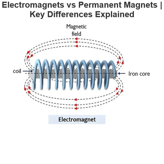
Electromagnets vs. Permanent Magnets: Understanding the Key DifferencesElectromagnets and permanent magnets are the two primary types of materials that exhibit magnetic properties. While both generate magnetic fields, they differ fundamentally in how these fields are produced.An electromagnet generates a magnetic field only when an electric current flows through it. In contrast, a permanent magnet inherently produces its own persistent magnetic field once it has been magnetized, without requirin
Edwiin
08/26/2025
Working Voltage in Power System
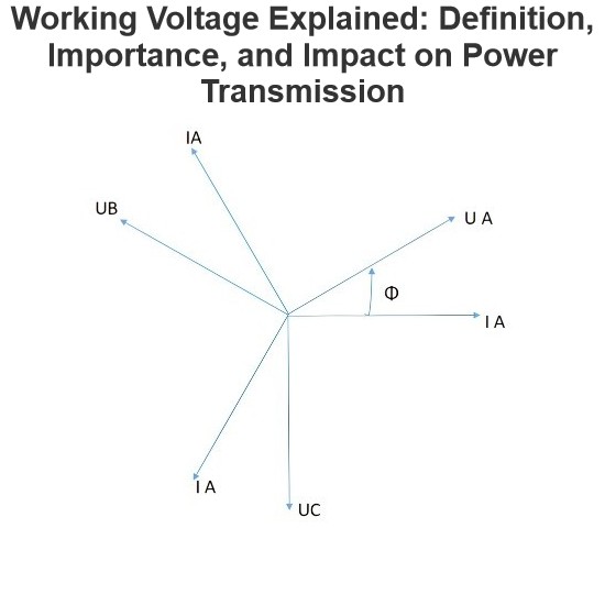
Working VoltageThe term "working voltage" refers to the maximum voltage that a device can withstand without sustaining damage or burning out, while ensuring the reliability, safety, and proper operation of both the device and associated circuits.For long-distance power transmission, the use of high voltage is advantageous. In AC systems, maintaining a load power factor as close to unity as possible is also economically necessary. Practically, heavy currents are more challenging to handle than hi
Encyclopedia
07/26/2025
What is a Pure Resistive AC Circuit?
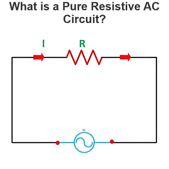
Pure Resistive AC CircuitA circuit containing only a pure resistanceR(in ohms) in an AC system is defined as a Pure Resistive AC Circuit, devoid of inductance and capacitance. Alternating current and voltage in such a circuit oscillate bidirectionally, generating a sine wave (sinusoidal waveform). In this configuration, power is dissipated by the resistor, with voltage and current in perfect phase—both reaching their peak values simultaneously. As a passive component, the resistor neither
Edwiin
06/02/2025
What is a Pure Capacitor Circuit?
Pure Capacitor CircuitA circuit comprising only a pure capacitor with capacitanceC(measured in farads) is termed a Pure Capacitor Circuit. Capacitors store electrical energy within an electric field, a characteristic known ascapacitance(alternatively referred to as a "condenser"). Structurally, a capacitor consists of two conductive plates separated by a dielectric medium—common dielectric materials include glass, paper, mica, and oxide layers. In an ideal AC capacitor circuit, the current
Edwiin
06/02/2025
Seed Inquiry
Download
Get the IEE Business Application
Use the IEE-Business app to find equipment, obtain solutions, connect with experts, and participate in industry collaboration anytime, anywhere—fully supporting the development of your power projects and business.